Remove and disassemble the brake valve (Fig. 1) in the following order:
- - remove the brake pedal return spring and disconnect the brake pedal rod from the lever;
- - disconnect all pipes from the brake valve;
- - disconnect the brake valve bracket mounting bolts and remove the brake valve;
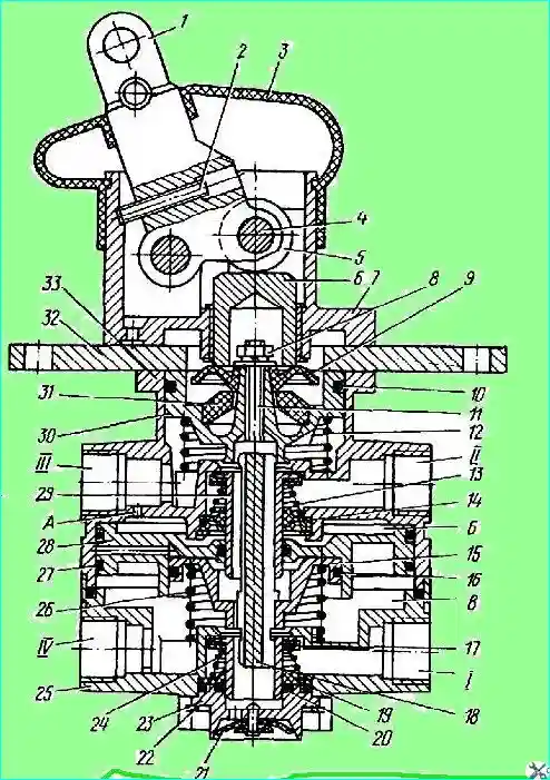
Fig. 1. Brake valve: 1; 2 - adjusting screw; 3 - protective cover; 4 - roller axis; 5 - roller; 6 - pusher; 7 - lever housing; 8 - nut; 9 - plate; 10, 16, 20, 27 - sealing rings; 11 - stud; 12, 13, 24, 26 - springs; 14, 19 - guides; 15 - small piston; 17 - lower section valve; 18 - small piston pusher; 21 - atmospheric outlet valve; 22 - retaining ring; 23 - atmospheric outlet housing; 25 - lower housing; 28 - large piston; 29 - upper section valve; 30 - upper piston; 31 - elastic element; 32 - plate; 33 - upper housing; (I, IV) - lower section terminals; II, III - terminals of the upper section
- - unscrew the bolts and remove the support plate 32 together with the housing 7 of the lever and the lever 1, remove the pusher 6;
- - remove the upper piston 30 with the balancing element in assembly;
- - remove the spring 12;
- - unscrew the bolts and separate the upper housing 33 and the lower housing 25;
- - remove the large piston 28 and the small piston 15 in assembly, then remove the small piston from the large one, remove the spring 26;
- - remove the retaining ring 22 and take out the seal, support ring, spring 24 and the housing with the valve 17 of the lower section;
- - remove the retaining ring and remove the outlet window, support ring and upper section valve assembly;
- - remove lever 1 of the brake valve, for which remove the axis;
- - when installing the upper piston, measure the distance "C" (Fig. 2), the protrusion of the tail of the small piston above the valve. Using the adjusting screw on the upper piston, set the distance d = C + 0.8 mm
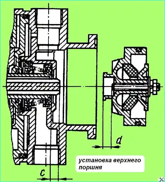
fig. Installing the upper piston
- - install the upper piston 30 (see Fig. 1);
- - assemble the valve with the support plate and lever;
- - put on the protective cover.
After assembly, the operation of the brake valve must be tested on a stand at an air pressure of 687 kPa in the system. The test diagram is shown in Fig. 3.
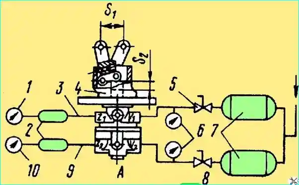
Fig. Brake valve testing circuit: 1, 6, 10 - pressure gauges; 2, 7 - cylinders; 3 - first circuit; 4 - brake valve; 5, 8 - shut-off valves; 9 - second circuit; S1 - lever stroke; S2 - pusher stroke
The testing procedure is as follows:
- — connect the pipes to terminals 11* and 12*. Press the lever several times until it stops (stroke S, min = 31.2 mm).
Air permeability through the terminals must be good.
With the lever released, check terminals 21*, 22* and 3* for leaks using soap emulsion;
connect terminals 21, 22 to the cylinders. When the lever is pressed smoothly, the first circuit should be triggered after the lever stroke of (5.7+1.5) mm, which corresponds to the pusher stroke of (2.3+0.6) mm.
The initial pressure jump in the first circuit should not exceed 20 kPa;
When the pressure in the first circuit reaches 50 kPa, the pressure in the second circuit should be at least 245 kPa.
The pressure lead in the first circuit relative to the pressure in the second circuit may be maintained over the entire pressure range, but not exceed 25 kPa.
The initial pressure jump in the second circuit should not exceed 20 kPa;
- - the lever stroke up to the pressure of 294 kPa in the first circuit should be (17.2d: 1.7) mm, which corresponds to the pusher stroke of (6.9±0.7) mm;
- - the lever stroke up to the pressure of 687 kPa in the first and second circuits should be (24±2.4) mm, which corresponds to the pusher stroke of (9.6±1) mm;
- - the total lever stroke to the stop should be (34.6±3.5) mm, which corresponds to the pusher stroke of (13.9+1.4) mm;
- - when smoothly pressing the lever, after the initial jump, the pressure in each circuit should smoothly increase, and when released, smoothly decrease. The stepwise pressure reduction should not exceed 294 kPa;
- — if the first or second circuit fails, the remaining circuit should remain fully operational;
- — check the valve for leaks in the inlet position.
Installing the valve and on the car is carried out in the reverse order of removal. It is possible to install the brake valve (Fig. 4).
Brake valve modification No. 2
Remove and disassemble the brake valve (Fig. 4) in the following order:
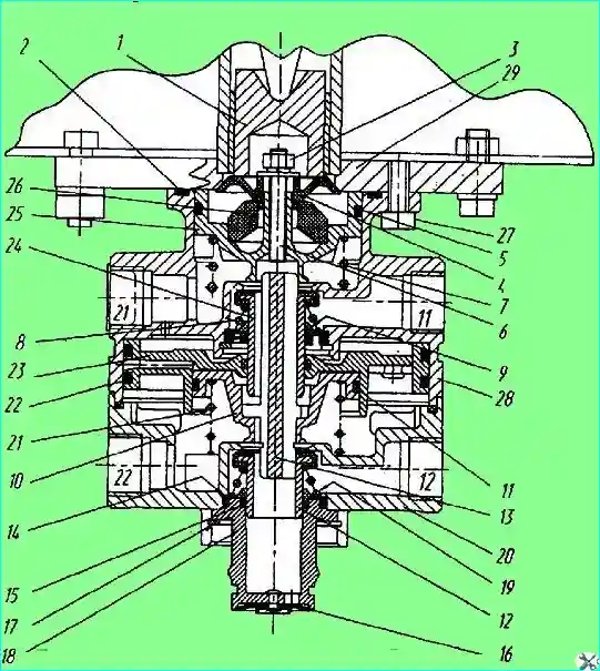
Fig. Brake valve: 1 - pusher; 2 - sealing ring; 3 - nut; 4 - plate; 5 - sealing ring; 10 - small piston; 11 - sealing ring; 12 - lower section valve; 13 - small piston pusher; 14 - support ring; 15 - sealing ring; 16 - atmospheric outlet valve; 17 - retaining ring; 18 - atmospheric outlet housing; 19 - spring; 20 - lower housing; 21 - spring; 22 - sealing ring; 23 - large piston; 24 - upper section valve; 25 - upper piston; 26 - elastic element; 27 - bolt; 28 - upper housing; 29 - bracket
- — lift the vehicle cabin;
- — disconnect all pipes from the brake valve;
- - unscrew bolts 27 and remove the brake valve, preventing the plunger 1 from falling out;
- - remove the upper piston 25 with the elastic element 26 in assembly;
- - remove spring 7;
- - unscrew bolts and disconnect the upper housing 28 and the lower housing 20;
- - remove spring 21, large piston 23 in assembly with small piston 10, and then remove the small piston from the large one;
- - remove retaining ring 17 and remove the housing of the atmospheric outlet 18 with sealing rings, support ring 14, spring 19 and lower section valve 12;
- - remove the retaining ring and take out the seal, support ring 9, spring 8 and upper section valve 24.
Assemble the valve in the reverse order of disassembly.
Before installing the upper piston, measure the distance "C" (Fig. 2) - the protrusion of the tail of the small piston above the valve.
Using the adjusting screw on the upper piston, set the distance d = c + 0.8 mm and fix the adjusting screw.
After assembly, it is necessary to check the operation of the brake valve on the stand at an air pressure in the system of 0.7 MPa (7.0 kgf/cm²).
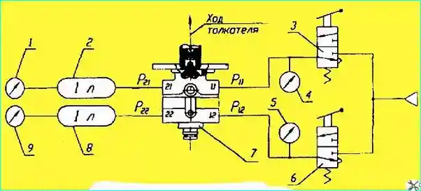
Fig. Brake valve connection diagram during testing: 1, 4, 5, 9 - pressure gauges; 2, 8 - air cylinders; 3, 6 - valves; 7 - brake valve; 11, 12 - compressed air inlets; 21, 22 - compressed air outlets; P11, P12 - inlet pressure; P21, P22 - outlet pressure
The test diagram is shown in Fig. 5.
The check procedure is as follows:
- — connect the pipelines, plug the unused terminals. Press the plunger three times until it stops.
With the plunger released, check terminals 21, 22 and 23 for leaks using soap emulsion;
- - connect terminals 21 and 22 to the cylinders and smoothly press the plunger.
The first circuit (upper) should operate after the plunger has traveled 1.9-3.0 mm. The initial pressure jump should not exceed 0.02 MPa (0.2 kgf/cm²);
- - when the pressure in terminal 21 reaches 0.05 MPa (0.5 kgf/cm²), the pressure in terminal 22 should be no less than 0.025 MPa (0.25 kgf/cm²).
The pressure lead in terminal 21 in relation to the pressure in terminal 22 can be maintained over the entire pressure range, but not exceed 0.025 MPa (0.25 kgf/cm²).
The initial pressure jump in terminal 22 should not exceed 0.02 MPa (0.2 kgf/cm²).
- when the pressure in terminal 21 reaches 0.3 MPa (3.0 kgf/cm²) the pusher stroke should be (5.8-8.0) mm;
- when reaching a pressure of 0.75 MPa (7.5 kgf/cm²) in terminal 21, the pusher stroke should be (8.4-10.8) mm;
the total pusher stroke to the stop should be (12.5-15.7) mm;
- — when smoothly pressing the pusher, after the initial jump, the pressure in each circuit should smoothly increase, and when released, smoothly decrease;
- — check the tightness of the valve with the pusher pressed all the way;
- — check the tightness with the pusher pressed all the way of the first circuit in the absence of pressure in the second circuit, and then the tightness of the second circuit in the absence of pressure in the first.
Installing the valve in reverse order.


