All-mode, centrifugal type, changes fuel supply depending on the load, maintaining the engine crankshaft speed set by the driver
It is installed in the rear part of the high-pressure fuel pump and is driven by the camshaft via gears.
The drive gear 20 is mounted on the cone of the camshaft.
Rotation from the pump shaft to the drive gear is transmitted through rubber crackers 19.
The driven gear is made as a single piece with the roller 16 of the weight holder and is installed in the cup 15 on two ball bearings.
The weight holder 7 is pressed onto the roller 16, on the axes of which the weights 22 swing.
The weights rest with their rollers on end face of coupling 27 which transmits the force of the loads via thrust bearing and heel 37 to power lever 43 suspended together with double-arm lever 5 on axis 11.
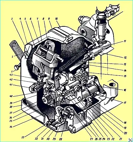
Speed regulator: 1 - minimum speed limiting bolt; 2 - regulator control lever; 3 - double-arm lever adjusting screw; 4 - inspection hatch cover; 5 - double-arm lever; 6 - regulator spring; 7 compensation spring; 8 - spring lever, 9 - regulator cover; 10 - regulator housing; 11 - lever axis; 12 - rack; 13 - rack rod; 14 - rack lever spring; 15 - cup; 16 - weight holder shaft; 17 - weight roller; 18 - pinion bushing; 19 - cracker; 20 - pinion; 21 - pinion bushing flange; 22 - governor weight; 23 - ball; 24 - weight coupling; 25 - lever shaft; 26 - cover; 27 - thrust heel axis; 29 - retainer spring; 30 - linkage axis; 31 - linkage screw; 32 - linkage retainer; 33 - power adjustment screw; 34 - linkage; 35 - lever; 36 - corrector; 37 - thrust heel, 38 - linkage bracket; 39 - governor earring; 40 - adjusting bolt; 41 - buffer spring housing; 42 - buffer spring; 43 - power lever
The coupling with the thrust heel assembly rests on one end through 27 balls on the guide surface of the holder, and is suspended by the other end on the earring 39, fixed on the power lever 43.
The heel of the regulator is connected by a common axis with the lever 35 of the rack and through the rod 13 with the rack 12 of the fuel pump.
The spring 24 of the rack lever is attached to the upper part of the rack lever, and a pin is pressed into the lower part, which enters the groove of the linkage 34.
The shaft 25 is rigidly connected to the control lever 2 and the lever 8 of the spring.
The spring 6 of the regulator is hooked to the spring lever and the two-arm lever 5, the force of which is transmitted from the two-arm lever to the power one through the adjusting screw 3.
There is an adjusting bolt 40 on the power lever, which rests against the shaft of the regulator lever.
The engine speed mode is set by the control lever 2, which is connected to the fuel supply control pedal by means of rods.
When the pedal is pressed, the lever 2 rotates at a certain angle and, through the lever 8 rigidly connected to it, causes an increase in the tension of the spring 6, under the action of which the rack moves towards increasing the fuel supply and the engine crankshaft speed increases.
This occurs until the centrifugal force of the weights balances the tension force of the spring 6, i.e. until a stable engine operating mode is established.
Repair of the regulator
The crankshaft speed regulator should not be completely disassembled during repairs.
The weight holder unit is not disassembled unless necessary, since pressing can damage the parts.
In addition (even in case of disassembly) it is necessary to strictly observe the completeness of the loads selected according to the static moment.
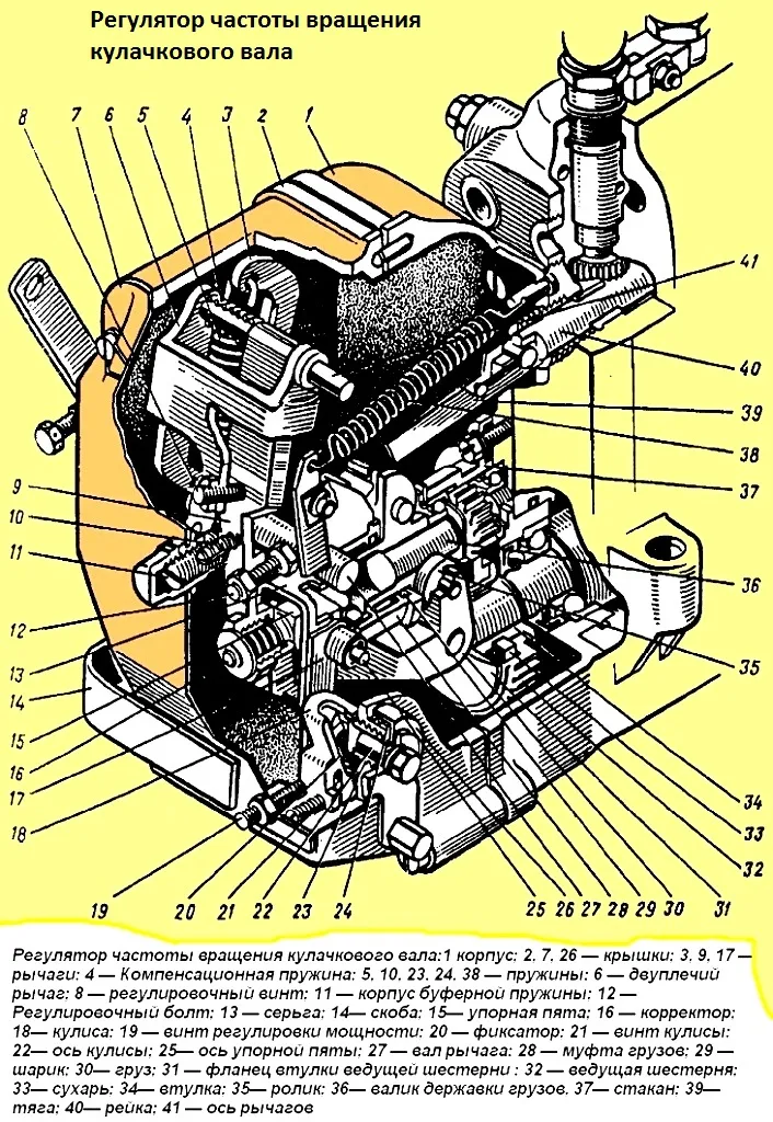
Fig. 2. Camshaft speed regulator: 1 - housing; 2, 7, 26 - covers; 3, 9, 17 - levers; 4 - compensation spring; 5, 10, 23, 24, 38 - springs; 6 - double-arm lever; 8 - adjusting screw; 11 - buffer spring housing; 12 - adjusting bolt; 13 - earring; 14 - bracket; 15 - thrust heel; 16 - corrector; 18 - linkage; 19 - power adjustment screw; 20 - lock; 21 - linkage screw; 22 - linkage axis; 25 - thrust heel axis; 27 - lever shaft; 28 - weight coupling; 29 - ball; 30 - weight; 31 - drive gear bushing flange; 32 - drive gear; 33 - cracker; 34 - bushing; 35 - roller; 36 - weight holder shaft; 37 - cup; 39 - rod; 40 - rack; 41 - lever axis
Disassemble the speed controller in the following sequence: remove the inspection hatch cover, use tweezers to disconnect spring 38 from the rack lever, disconnect the spring bar from the fuel injection pump rack 40 and remove cover 2 of the controller.
When removing the cover, it is necessary to protect balls 29 located in the trapezoidal groove of the weight coupling from loss.
Having unscrewed the fastening bolts cup 37, remove the cup together with the weight holder and weights 30.
Removal and disassembly of weights is not allowed.
After this, unscrew the gear fastening nut and remove gear 32 with flange 31 and crackers 33 from the gear bushing; the bushing is removed from the camshaft of the fuel pump using a puller (Fig. 3).
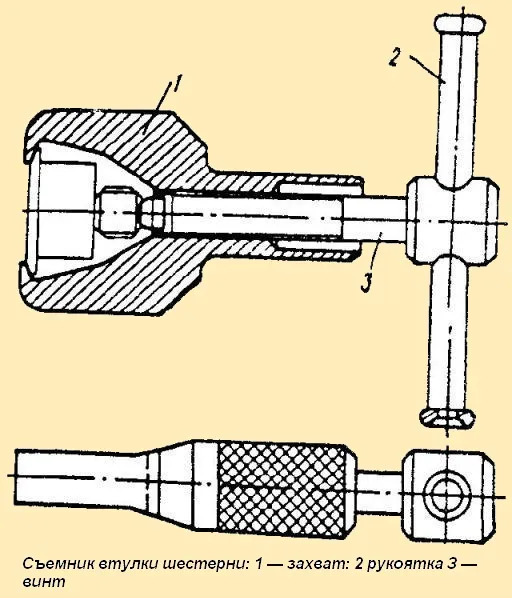
Fig. 3. Gear bushing puller: 1 - grip; 2 - handle; 3 - screw
The regulator cover must be disassembled in the following order: unscrew the plug screws, remove the axle 41 (see Fig. 1) of the levers, remove the regulator lever 9 with the clutch 28 of the weights and the rack lever 17, disconnect the double-arm lever 6 from the regulator spring 5, remove the spring, unscrew the bolt and the axle of the linkage bracket and remove the linkage 18 and the linkage bracket 14, remove the shaft 27 of the spring lever together with the regulator control lever, having first loosened the spring lever mounting bolt, moved the spring lever along the shaft and removed the key.
To disassemble the linkage, it is necessary to turn the axle 22 relative to the linkage 18, thereby recessing the retainer 20. Insert a plate 1.5 - 2 mm thick into the resulting gap between the end of the retainer and the cutout of the axle and, turn the axle to its original position and remove it.
To disassemble the cup together with the weight holder roller, it is necessary to turn the spring ring and remove the weight holder roller 36 together with the holder and bearings from the cup, press the front (small) bearing off the roller.
Pressing the rear bearing off the weight holder roller, as well as disassembling the weights without necessity is not recommended. When removing the weights, they must be reinstalled in the same sequence.
The assembled weight holder must be inspected and measured without disassembling to determine its suitability for further use.
The engagement gap between the teeth of the holder shaft and the drive gear must not exceed 0.25 mm, with a nominal value of 0.085 mm.
The check is carried out when installing the parts in their working places.
The gap between the weight bushings and the weight axes pressed into the holder must not exceed 0.24 mm, with a nominal value of 0.035 mm.
The gap between the weight roller transmitting the force to the coupling and the roller axis must not exceed 0.3 mm, with a nominal value of 0.025 mm.
The outer diameter of the weight roller must be at least 15.8 mm.
The weight holder is made of 20 L steel. The neck for the weight coupling balls is case-hardened to a depth of 0.2-0.6 mm and hardened with heating to a hardness of at least HRC56. The hardness of the casting is HB 121 – 187.
The main defects that occur during operation are the following: wear of the neck for the weight coupling balls and wear of the holes for the weight axes.
The neck for the weight coupling balls is restored when it is worn to a diameter of less than 23.86 mm using the chromium plating method. To do this, grind the neck as cleanly and chrome plate to a diameter of 24.15-0.02 mm
After final grinding over a length of 18 mm, the size should be 24.15-0.02 mm and the surface roughness should be 0.32 µm.
The size of the holes for the axles of the weights is restored by installing bushings. To do this, the holes are drilled and reamed along the jig to a diameter of 10+0.010 over a length of 26 mm.
The bushings are pressed into the reamed holes with an interference fit of 0.015 - 0.02 mm.
Then the holes in the bushings are drilled and reamed to a diameter of 8-0.012 mm and the holes are countersunk on both sides to a depth of 1 mm at an angle of 90°.
The surface roughness of the holes after processing should be 2.5 μm.
When processing the holes, the jig is based on the hole for the weight holder roller.
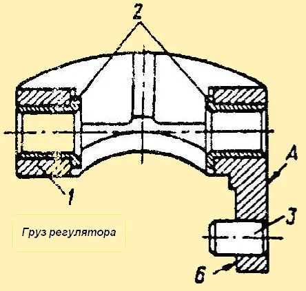
Fig. Regulator weight
The assembled regulator weight may have the following defects: loose fit of bushings 2 (Fig. 4) in the hole of weight 1 of the regulator, wear of the hole in the bushing under the weight axis and loose fit of axle 3 of the weight roller or wear of the roller axle diameter under the regulator weight.
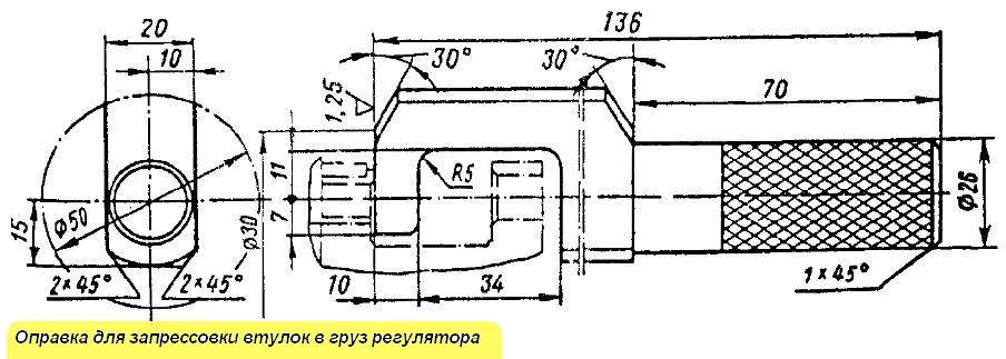
Fig. Mandrel for pressing bushings into the regulator weight
Loose fit of the bushings and the axle is checked by light blows with a copper mandrel. If they are loose, they are replaced.
Also, if the holes in the bushings are worn to a diameter of more than 8.085 mm and the roller axis to a diameter of less than 6.95 mm, they are replaced.
Bushings 2 are pressed in on the press from the inner ends of the lugs with a mandrel (Fig. 5) until it stops against the end.
The roller axis must be pressed in from the side of surface B (see Fig. 3) flush with surface A.
To check the alignment of the surfaces of the holes in the bushings, use a control mandrel with a diameter of 8+0.008 mm, which must freely pass through both holes.
The regulator body and made of aluminum alloy AL-10V. Hardness of the alloy HB 80 - 120.
The main defects that occur during operation are the following: loosening of the fit of the mounting pins, wear of the hole for the camshaft bearing race, wear of the holes for the bearing shaft of the weight holder and damage to the threaded holes.
Loosening of the fit of the pins is determined by light blows of a copper mandrel.
A new pin of a repair (enlarged) size is installed on the seating surface. To do this, the hole for the pin is reamed to a diameter of 6.2-0.030 mm to a depth of 10 mm and the pin is pressed in, which should protrude above the plane by 6 mm.
The hole for the bearing race is restored by surfacing. To do this, the housing is heated to a temperature of 300 - 350 ° C for 15-20 min, and the surface to be welded is cleaned of the oxide film.
The welding is carried out with an electrode of the OZA-2TuOSZ brand with a diameter of 4 mm.
After welding, the body is heated to a temperature of 300-350 ° C for 10-15 minutes and then loaded into a drip pan, where it is cooled for four hours.
This entire process is carried out to ensure high-quality welding and relieve internal stresses that arise after welding.
Then bore the hole for the bearing race to a diameter of 47+0.007 mm over a length of 14 mm and bore a chamfer of 1x45 °.
The hole for the bearing of the weight holder roller is bored to a diameter of 30+0.045 mm to a depth of (5 ± 0.1) mm and 0.5x45° chamfers in the faceplate on a lathe.
If the thread in the holes for the regulator cover mounting bolts (M6x1) or for the bearing cup mounting bolts of the holder roller (M8 x 1.25) is damaged by more than two threads, it is repaired by installing brass inserts on epoxy glue.
Assemble the speed regulator in the following order:
insert the key, install the gear sleeve on the fuel injection pump camshaft, assemble the gear with crackers and flange, put it on the sleeve, check the ease of its rotation on the sleeve, tighten the gear mounting nut [torque 10 - 20 Nm (1-2 kgfm) and lock.
The play in the damping device is not allowed.
Next, install the shaft with the bearings pressed onto it and the weight holder into the cup, lock it with a spring ring, and check the ease of rotation of the shaft.
The front bearing should be pressed onto the shaft so that the thickened part of the inner bearing race rests against the shaft collar.
After this, install the cup into the regulator body, securely tighten the cup mounting bolts, carefully lock them with washers, assemble the regulator cover in the reverse order of disassembly, and install the cover on the regulator.
When assembling the regulator cover, take into account that:
- - the regulator lever and the double-arm lever should swing freely on the axis relative to each other;
- - the axial play of the spring lever shaft should be 0.1-0.3 mm;
- - to install 27 balls in the groove of the weight coupling, use UM or TSIA-TIM 203 grease or their substitutes;
- - the fuel supply adjustment screw must be turned out flush with the boss of the regulator cover;
- - when assembling the corrector, the pre-tension of the corrector spring must be within 85-95 N (8.5-9.5 kgf).
Adjustment is made using washers installed between the bottom of the corrector housing and the spring.
The assembled corrector is installed flush with the support platform of the regulator lever and locked with a nut.
The weight coupling bearing must be pressed onto the heel so that the thickened part of the inner race of the bearing rests against the shoulder of the heel.
In the assembled regulator, all parts must move without jamming, the control lever and The linkage bracket should smoothly return to its original position under the action of the springs.
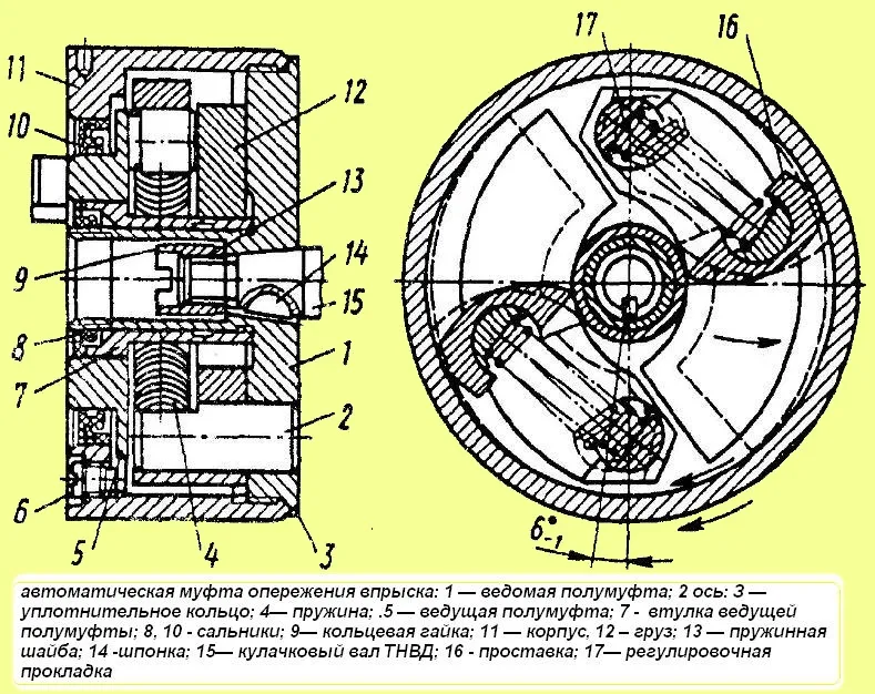
Fig. Automatic injection advance clutch: 1 - slave half-coupling; 2 - axle; 3 - sealing ring; 4 - spring; 5 - leading half-coupling; 7 - leading half-coupling bushing; 8, 10 - oil seals; 11 - housing; 12 - weight; 13 - spring washer; 14 - key; 15 - high-pressure fuel pump camshaft; 16 - spacer; 17 - adjusting shim
The automatic injection advance coupling (Fig. 6) is disassembled on a special device (Fig. 7).
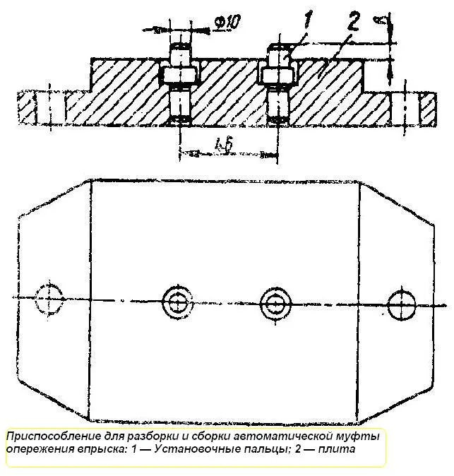
Fig. Devices for disassembling and assembling the automatic injection advance coupling: 1 - installation pins; 2 - plate
First, the driven half coupling 1 is caulked in two places (see Fig. 5), the plug screws 6 are unscrewed from the coupling body and the oil is drained.
During caulking, it is necessary to take into account the need to preserve the supporting sealing end face of the driven half coupling. For this, the calculation the stamping is carried out without bringing the surface of the stamped areas to the level of the main end.
When unscrewing the half coupling, the stamped areas themselves are installed flush with the main surface.
Then unscrew the housing 11 of the coupling from the driven half coupling 1, remove the leading half coupling 5 (see Fig. 5) with spacers 16, weights 12, springs 4, gaskets 17 and press out the seals 8 and 10 from the coupling housing and the leading half coupling.
Considering that the coupling weights are selected for installation in the unit based on the static moment, it is necessary to maintain their paired completeness during subsequent installation in the injection advance coupling unit.


