The vehicles are equipped with two sound signals: a pneumatic one mounted on the roof of the cab, and an electric one consisting of two signals: a low and a high tone.
A noise relay-buzzer is also installed, signaling a decrease in air pressure in the brake system circuits and clogging of the air and oil filters of the engine, which is determined by the change in pressure when the filters are clogged.

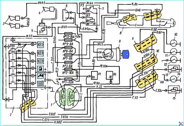
Sound signaling diagram: 1 - pressure indicator; 2 - control lamp unit; 3 electric signals; 4 - pneumatic signal; 5 - electro-pneumatic valve; 6 buzzer: 7 - relay P3 for switching on signals; 8 - steering column switch; 9 - switch-lock for instruments and starter; 10 - sensor of indicator lamp for clogging of oil filter; 11 - sensor of indicator lamp for clogging of air filter; 12 - sensor of emergency air pressure in front circuit of brake system; 13 - sensor of pressure indicator in rear circuit; 14 - sensor of emergency air pressure in rear circuit of brake system; 15 - sensor of pressure indicator in front circuit; VI, VII, X — plug connectors
The wiring diagram for the sound devices is shown in Fig. 1.
The pneumatic signal is controlled by a button located on the right side of the steering column switch 8.
This button turns on the electro-pneumatic valve, which opens the access of compressed air to the signal.
The signal has two horns: high- and low-frequency.
When air is supplied to the signals, the vibrators begin to vibrate, producing a loud melodic sound.
The electric signal is turned on by the handle. located on the left on the steering column switch (the turn signal control handle).
When the handle is raised, the relay winding RZ is connected to ground (see Fig. 1), which turns on the sound signals.
Possible malfunctions of the sound signaling system
The pneumatic signal does not work:
- - Fuse No. 7 has blown - Replace the fuse
- - The solenoid valve has failed - Remove and replace the solenoid valve
The pneumatic signal makes a wheezing sound:
- - Low air pressure in the system - Pump air into the system
- - The signal vibrator has burst - Check and replace the relay
The electrical signals:
- - Fuse #13 has blown - Replace the fuse
- - Relay P3 has failed - Check and replace the relay
The sound level of electrical signals has decreased:
- The adjustment is out of order - Remove the signals and adjust
The signal makes a rattling sound:
- - A crack has appeared in the signal membrane - Remove the signal, disassemble and replace the membrane. Adjust the signal
The buzzer-noise relay does not signal a decrease in air pressure in the brake system:
- - Fuse No. 8 has blown - Replace the fuse
- - The buzzer-relay has failed - Replace the relay
In the sound signaling system, it is necessary to monitor the cleanliness of the sound signals; if they become dirty, they must be wiped with a dry cloth.
Adjustment of electrical signals is carried out only if they fail after repair or if the volume decreases.
Adjustment is carried out using adjusting nuts. Loosen the nuts and turn them until the best signal sound is achieved, then tighten the nuts.
Possible malfunctions of the sound signaling system and methods for eliminating them are listed in the table.
Vibrators fail in the pneumatic signal and must be replaced.
Repair of electrical signals usually comes down to replacing the membrane that has failed. The buzzer relay is not repaired, but must be replaced entirely.


