MAZ vehicle frame design and maintenance
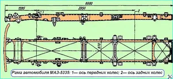
The vehicle frame is riveted and consists of two longitudinal beams (spars) of a channel shape with a variable cross-section, made of 8 mm thick low-alloy strip steel 22G2TYu
The frame side members (the largest cross-section size is З10х85), made by hot stamping, are connected in five places by crossbars using rivets.

Fig. 1. MAZ-5335 vehicle frame: 1 - front wheel axle; 2 - rear wheel axle
The cross members are stamped, made of low-alloy steel, the second and third are made of low-carbon steel.
The brackets for the front, rear and additional springs, side engine mounts, cabin mounts, steering, etc. are attached to the side members.
The design feature of the frame is the transfer of the fastening of all its power elements and, in particular, the brackets for the springs and cross members to the vertical walls of the side members in the most loaded places.
The use of high-strength low-alloy steel and the absence of riveted joints on the lower shelves of the side members made it possible to distribute stresses favorably and achieve high frame strength.
Frame maintenance
Frame maintenance consists of checking the bolted and riveted joints.
During vehicle operation, it is necessary to ensure that the geometric shape of the frame, the correct position and strength of its side members, cross members and brackets.
Violation of the geometric shape of the frame can lead to incorrect position or displacement of the vehicle units, which will cause excessive stress and increased wear of transmission and engine parts.
Loose rivets are detected by a rattling sound when tapping the rivet head with a hammer.
Rivets that have become loose must be cut off and replaced with new ones.
There should be no unpainted areas on the frame, as this can lead to corrosion, which reduces the fatigue strength of the frame.
Therefore, the frame must be periodically cleaned, inspected and painted over exposed and corroded areas.
Frame repair
The main defects of the frame can be: cracks in the side members and cross members, loosening of riveted joints, wear of spring brackets, longitudinal cracks in side members in the area of rivets.

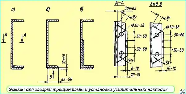
Fig. 2. Sketches for welding frame cracks and installing reinforcing pads
Cracks in side members and cross members are repaired by welding. Before welding, the crack must be prepared with an emery wheel at an angle of 75 - 90˚.
It is recommended to use electric arc welding with electrodes designed for low-alloy steel.
If there are cracks on the shelves that do not extend to the side member wall, in addition to welding the crack, install reinforcing pads made of low-alloy steel 8 - 10 mm thick on the inside or outside, weld them with longitudinal seams and rivet them with electric rivets.
Weld in accordance with the sketches (Fig. 2, a, b).
If the cracks extend to the side member wall, then, in addition to welding the crack itself, install an L-shaped reinforcement and then weld it (Fig. 2, c).
The frame is allowed to be repaired if there are no more than two cracks on one side member, reaching the middle profile.
A frame with more than two cracks on each side member that reach the middle of the profile, or one or more cracks on one of the side members that extend beyond the middle of the profile, cannot be repaired and must be replaced with a new one.
Rivets with torn heads are knocked out and replaced with bolts (if necessary, oval holes are reamed).
If cracks (no more than 3) appear in the side members from under the rivets, the ends of the cracks are drilled with a drill with a diameter of 5 - 7 mm to prevent their further spread. In this case, welding is not required.
If, when checking the riveted joints of the frame, a break in the rivet head is detected, it is necessary to knock the rivet rod out of the hole and install a new rivet.
It is permissible to install a heat-treated bolt with a nut and a spring washer of the appropriate diameter instead of a rivet, ensuring that the tightening torque of the nuts M16x1.5-200-240 Nm (20-24 kgfm) and nuts M14x1.5-160-180 Nm (16-18 kgfm).
The bolt must fit tightly in the hole.


