The wheel drive (Fig. 1) is a planetary gearbox consisting of spur gears with external and internal gearing
From the drive gear of the wheel transmission, rotation is transmitted to four satellites 14, evenly spaced in a circle around the drive gear.
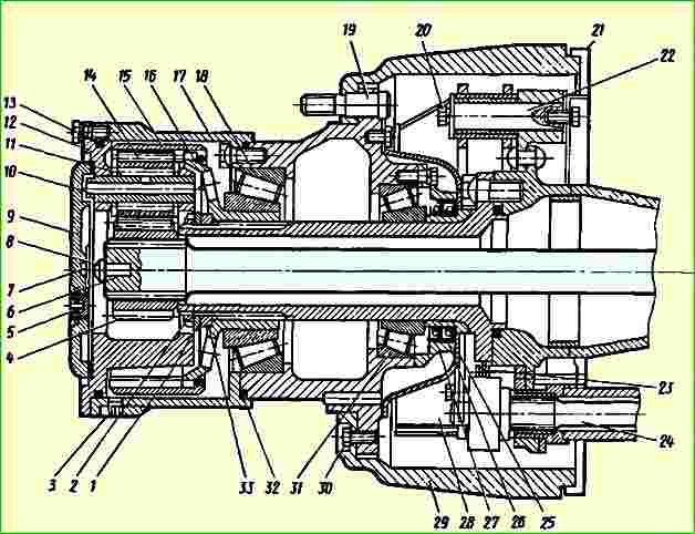
The satellites rotate on axles 10, fixed in the holes of the movable carrier 12, connected with bolts to the hub of the drive wheels, in the direction opposite to the direction of rotation of the drive gear.
Rotating on their axes, the satellites roll along the internal teeth of the driven gear 15, fixedly fixed by means of a hub 16 on the splined end of the axle beam axle.
The drive gear has a hole with involute splines that mate with the splines of the outer end of the axle shaft.
The axial movement of the drive gear on the axle shaft is limited by a spring lock ring. The axial movement of the axle shaft is limited by the block 7 and the axle shaft stop 8.
Satellites with needle bearings are mounted on an axle, placed in the coaxial holes of the carrier 12 and secured in it from axial movement by spring locking rings.
Washers are placed on the satellite axle to prevent the gears and bearings of the satellite axes from touching the carrier.
The driven gear 15 of the wheel transmission rests with its internal gear ring on the external gear ring of the driven gear hub 16, and the splined end of this hub is mounted on the splined part of the axle beam axle.
Such a connection does not allow rotation of the driven gear, while the axial movement of the gear is limited by a spring ring that fits into the groove of the ring gear of the driven gear and abuts against the inner end of the ring gear of hub 16.
Washers are placed on the satellite axle to prevent the gears and bearings of the satellite axes from touching the carrier.
The carrier is closed from the outside with a cover 9 and, in conjunction with the wheel hub, is sealed with a rubber ring 13.
Lubrication of gears and bearings of wheel drives is carried out with sprayed oil, which is poured through the hole in the cover 9, closed with plug 5.
The lower edge of this hole determines the required oil level in the wheel drive.
The drain hole, closed by plug 3, is made in the wheel hub, since the cavities of the wheel drive and the wheel hub communicate.
When the vehicle moves, the oil in the wheel drive cavity and wheel hubs is mixed and supplied to the gear bearings, wheel hubs and gears.
To improve the supply of lubricant to the bearings of the satellite axles, the axles are made hollow and have radial holes in them for supplying oil to the bearings.
The main gear of the MAZ-64227 middle drive axle consists of a central gearbox and planetary wheel gears located in the wheel hubs.
Repair of wheel drive and rear wheel hub
Disassembling the wheel drive and removing the rear wheel hub must be done in the following sequence:
- - loosen the rear wheel nuts;
- - install a jack under one side of the rear axle beam and lift the hub with wheels.
- - Place the stand and remove the jack;
- - unscrew the nuts securing the rear wheels, remove the clamps, outer wheel, spacer ring and inner wheel, having previously disconnected the valve extension mounting bracket;
- - drain the oil from the wheel drive by unscrewing the plug and remove cover 9 (see Fig. 1);
- - unscrew the mounting bolts and remove the 12th wheel carrier assembly with satellites;
- - remove axle shaft 6 together with the drive gear of the wheel drive;
- - remove the axes of 10 satellites one by one, supporting the satellites with bearings;
- - remove satellites 14 with bearings and support washers from the carrier;
- - use a special wrench to unscrew the locknut 2 of the bearings of the driven gear hub 16, remove the lock washer 1, unscrew the bearing nut 33 and remove the hub 16 together with the driven gear 15 and the inner race of the bearing 18;
- - supporting the hub 17 by the bearing ring 18, remove it with the brake drum 29 and the disc assembly.
If it is necessary to replace the oil seal and wheel bearing, then do the following;
- - remove the oil trap 25 and the oil seal cover 27, unscrewing the fastening bolts;
- - remove the oil seal from the cover and, using a special mandrel, press new oil seals into the cover, avoiding damage and distortion;
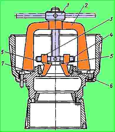
- - remove the inner rings of the outer bearings of the hub using a puller (see Fig. 2);
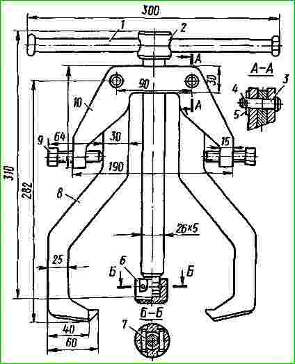
- - press out the outer rings of the outer and inner wheel bearings using the puller shown in Fig. 3.
If a leak is detected at the ring seal 32 (see Fig. 1) or the hub mounting bolts are loose, it is necessary to unscrew the bolts,, if necessary, replace the ring and tighten the bolts, followed by locking them with plates.
The wheel drive parts and the hub are washed and carefully inspected.
On the surface of the gear teeth, chipping of the cementation layer is not allowed.
If there are cracks or broken teeth, the gears must be replaced.
Installation of hubs and assembly of the wheel drive is carried out in the reverse order of disassembly.
After installing the hub, the bearing tension must be adjusted as follows:
When turning the hub, tighten nut 33 with a torque of 40 - 50 kgcm, then unscrew it 60 - 75˚ and check the hub for rotation. It should rotate freely, but without play;
- - after adjustment, install washer 1 (see Fig. 1), if the nut pin does not coincide with the washer hole, unscrew the nut until the nearest washer hole matches;
- - tighten locknut 2 with a torque of 40 - 50 kgcm.
The middle axle axle shafts are installed so that the short axle shaft is on the right side as the vehicle moves.
The device for installing the drive axle axle shaft is shown in Fig. 4.
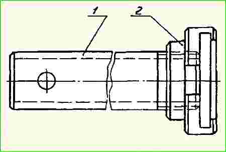
To install the axle shaft you need:
- 1. Place the nut of the device on the retaining ring of the axle shaft.
- 2. By rotating the handle of the device, ensure that the device with the axle shaft becomes one whole, i.e., obtain tension.
- 3. Relying on the final drive gear, using it as a fulcrum, and the axle shaft with the device as a lever, it is necessary to engage the second end of the axle shaft with the spline of the differential gear of the drive axle.
- 4. After completing the previous operation, carefully engage the side gears with the axle gear.
- 5. Remove the device from the retaining ring and install the axle shaft in its place.
")

")
")
")
")
")
")
")