Adjusting the central gearbox
Adjust with the gearbox removed in the following sequence:
- — adjust the tension of the tapered bearings of the leading bevel gear;
- — adjust the differential bearings;
- — adjust the engagement of the bevel gears by the contact patch and lateral clearance, then readjust the differential bearings.
In this case, to avoid disrupting the initial bearing adjustment, nuts 17 of Fig. 1 unscrew and screw in at the same angle.
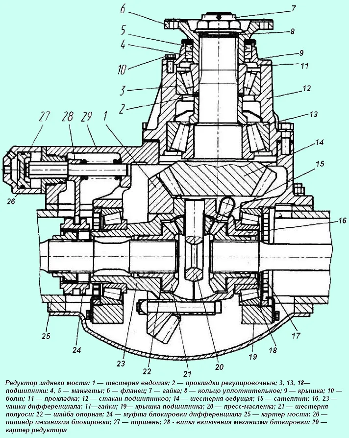
To adjust the bearings of the leading bevel gear, remove the leading bevel gear with the bearing housing assembly. To do this, in the rear axle gearbox housing, unscrew the bolts securing the cup 12 (see Fig. 1) of the bearings and use the dismantling bolts to remove the cup 12 with the gear.
In the middle axle gearbox, unscrew the bolts securing the gear housing and use the dismantling bolts to remove the gear housing assembly with the input shaft, bend back the locking plates, unscrew the nuts securing the bearing cup and remove the bearing cup assembly with the leading bevel gear;
- — use an indicator to determine the axial clearance in the bearings;
- — secure the leading gear in a vice, protecting it from damage with gaskets made of soft metal;
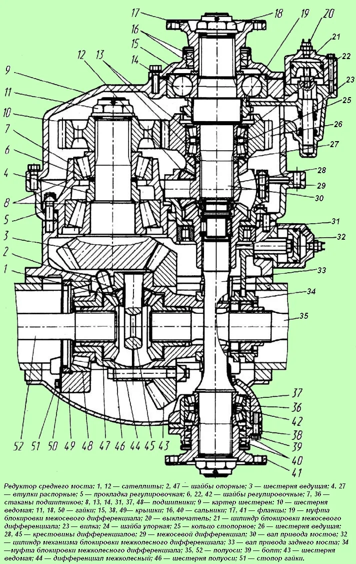
- — remove flange 6 (see Fig. 1), cover 9 with seals 4, 5 or gear 10 (see Fig. 2), the inner ring of the bearing closest to the shank and adjusting lining 2 (see Fig. 1);
- — measure the thickness of the adjusting lining and calculate its required thickness to eliminate axial play and obtain a preliminary bearing tension (the reduction in lining thickness should be equal to the sum of the axial play measured by the indicator and the bearing tension value equal to 0.03-0.05 mm);
- — grind the adjusting lining to the required value and assemble the drive gear without securing the cover with the cuffs;
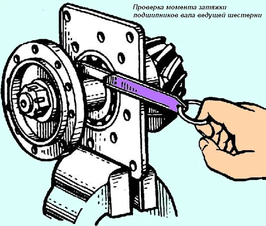
- — when tightening flange nuts rotate the bearing cup to correctly position the rollers in their housings;
- — check the bearing tension by the value of the bearing cup turning torque, which should be equal to 1-3 Nm (0.1-0.3 kgf-m) (Fig. 3).
If the bearings have a normal pre-tension, remove flange 6 (Fig. 1), install cover 9 with the seal and finally assemble the unit.
Adjust the differential bearing tension with the drive gear removed using nuts 17 (see Fig. 1) and 50 (see Fig. 2).
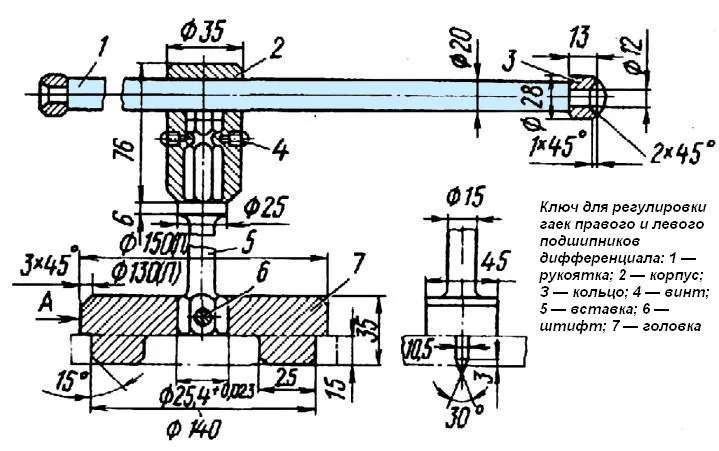
Tighten the nuts to the same depth until the desired pre-tension is achieved, without disturbing the position of the driven gear using a special key (Fig. 4).
Bearing preload is determined by the torque required to turn the differential, which should be within 2-5 Nm (0.2-0.5 kgf with the drive gear removed).
This torque is determined with a special torque wrench or by measuring the force applied to the radius of the differential cups and equal to 23-57 N (2.4-5.8 kgf).
Checking and adjustment of the engagement of bevel gears is as follows:
- — before installing the bearing housing with the drive gear in the gearbox housing, wipe the teeth of both bevel gears and apply a thin layer of paint to the side surfaces of three or four teeth;
- — using the table as a guide, adjust the engagement of the bevel gears. The movement of the drive gear is ensured by changing the number of adjusting shims under the flange of the drive gear bearing cup.
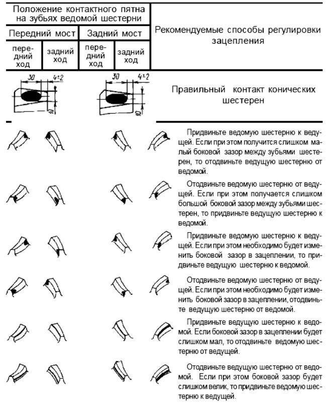
To move the driven gear, use nuts 17 (see Fig. 1) or 50 (see Fig. 2), so as not to disturb the adjustment of the tension in the differential bearings, tighten (loosen) the specified nuts by the same angle.
Adjust bearings 13 in the following sequence:
- — disconnect the cardan shaft from the flange 17;
- — remove the differential lock mechanism;
- — unscrew the gear housing mounting bolts and remove the housing assembly with the center differential;
- — disassemble the center differential, remove the drive gear and take the bearings out of the gear;
- — wash the parts in diesel fuel, and lubricate before assembly;
- — install the inner bearing in the gear seat 26;
- — install the spacer ring 25 and the outer race of the outer bearing;
- —- to ensure preliminary tension in the bearings, reduce the thickness of the set of washers 22 by the amount of axial clearance plus 0.02-0.03 mm and install them in place;
- — install the inner race of the bearing in assembled with a separator.
To check the preload in the bearings, install gear 26 with bearings on the press table through a mandrel (with support on the end of the inner race of the inner bearing) and compress the bearings with a slight force.
A crosspiece 28 and spacer sleeve 27 assembled with a gear can be used as a mandrel. By rocking, check for axial clearance and ease of turning the gear.
The force of turning the drive cylindrical gear, applied to its outer diameter, should be within 5.4-22N (0.55-2.2 kgf).
Adjustment of bearings 37 of the output shaft 33 is also performed by changing the set of adjusting washers 42 in the following sequence:
- — unscrew bolts 39 and remove the output shaft 33 with the bearing cup;
- — wash the parts in diesel fuel and lubricate before assembly;
- — clamp the shaft in a vice, install the inner race of the inner bearing with the separator on the shaft;
- — install the cup 36 assembled with the outer bearing races;
- — install the required set of adjusting washers 42, the thickness of which is reduced by the value of the axial clearance plus 0.02-0.03 mm;
- — install the separator and the inner race of the outer bearing;
- — install flange 41, tighten the nut. Check for axial play by rocking and turning flange 41.
The turning force applied at the radius of the holes in the flange should be within 6.4-25.5 1-1 (0.65-2.6 kgf).
After adjustment, unscrew the nut and remove flange 41, install cover 38 of the seal and, having assembled the unit, tighten the flange nut. In this case, the holes for the cotter pin must match the slot in the nut.
Then cotter pin the nut, install the shaft with the bearing unit and flange assembly in place.
Adjusting the interwheel and interaxle differential locking mechanisms
The interwheel differential locking mechanism is adjusted on the assembled central gearbox, before installing it in the axle housing, in the following order (Fig. 1):
- — measure the gap between the ends of the coupling 24 and the differential cup, the value of which should be 10.5 mm, while the coupling 24 should be held coaxially with the cup 23 using a mandrel;
- — unscrew the bolts securing the pneumatic cylinder 26 and remove it together with the piston;
- — having unscrewed the nut of the fork rod screw, tighten or unscrew the screw by the amount of the required fork movement to ensure a gap of 10.5 mm, tighten the nut and install the cylinder.


