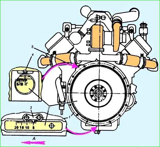
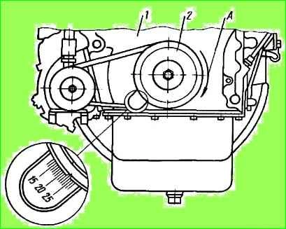
To adjust the fuel injection advance angle, there are two hatches on the flywheel housing (see Fig. 1), and the angle values are marked on the flywheel in two places
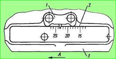
For the lower indicator 3, these values are made on the flywheel in digital terms, and for the side indicator 4 - in alphabetical expression, while the letter “A” corresponds to the value in digital terms of 20°; letter “B” - 15°; letter “B” -10°; letter "G" - 5°.
Rotate the engine crankshaft clockwise (as viewed from the fan side) until the marks on the crankshaft pulley and the timing gear cover or on the flywheel with the indicator align, corresponding to the installation angle of the fuel injection advance:
In this case, the valves in the 1st cylinder must be closed.

You can rotate the crankshaft with a wrench using the crankshaft pulley mounting bolt or a crowbar using the holes in the flywheel (Fig. 2) with the flywheel housing hatch cover removed.
At the moment of aligning the marks, mark “A” on the end of the coupling (Fig. 3, 4) should align with mark “B” on the indicator. If the marks are not aligned, adjustments must be made.
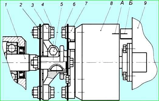
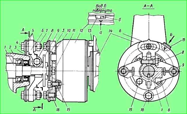
The procedure for adjusting the injection advance angle of YaMZ-236NE2, BE2 engines (Fig. 3):
- - loosen bolt 2 of the terminal connection: flange 3 - drive coupling half 1;
- - by turning the damper coupling, align the indicated marks;
- - without disrupting the aligned position of the marks, tighten the terminal connection bolt with a torque of 16-18 kgcm. In this case, the deviation of the plate package from the position in one plane should be within ±1 mm.
Measurement should be carried out near the places where the plates are attached.
If corrugations appear on the plates 4, they are eliminated by alternately loosening and then tightening with a torque of 11-12.5 kgcm the four bolts 5 securing the plates to the flange of the coupling half and to the damper coupling;
- - check that the injection advance angle is set correctly.
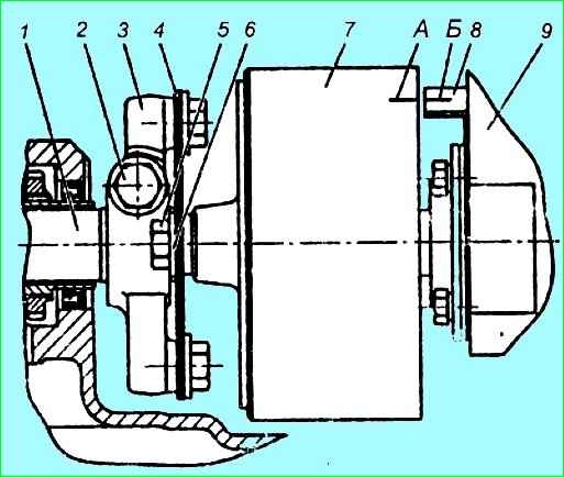
The procedure for adjusting the injection advance angle of YaMZ-236N, B, NE, BE engines (Fig. 4):
- - check the tightness of the coupling half 3 on the drive shaft 1 and the tightening of the terminal bolt 5 (tightening torque 43.2--58.9 Nm (4.4...6 kgcm));
- - unscrew (loosen) two bolts 4 and by turning the advance clutch, use the oval holes on the flange of the coupling half to align the marks “A” and “B”;
- - 236NE2 BE2: 6˚ +1˚ on engines equipped with a V-shaped fuel injection pump; the installation angle of fuel injection advance is 6˚… 7˚
- - 236NE, BE: 13˚±1˚
- - 236N, B: 15˚ +1˚ on engines equipped with a V-shaped fuel injection pump, setting fuel injection advance angle 10˚…11˚
- - turn the crankshaft and check that the injection timing is set correctly. The discrepancy between the marks should be no more than one division or 1° of rotation of the crankshaft.
Check the presence of oil in the fuel injection advance clutch (YaMZ-236N, B, NE, BE engines), and, if necessary, add oil; to check, set the clutch with its holes in the upper position and unscrew the plugs.
When the coupling is slowly turned 70°, oil should begin to flow out of one hole lo. After adding oil, tighten the plugs.
The fuel injection advance angle must be set using a momentoscope installed on the fitting of the 1st section of the fuel injection pump.
The injection advance angle should be:
- - for the YaMZ-238FM engine - 23 ˚;
- - for engine 51M3-238PM - 22 °.
The fuel injection advance angle must be set in the following order:
- - make sure that the marks on the injection advance clutch and the drive half of the fuel pump drive are in the correct relative position. The marks must be on one side;
- - remove the high pressure pipe of the first section of the injection pump;
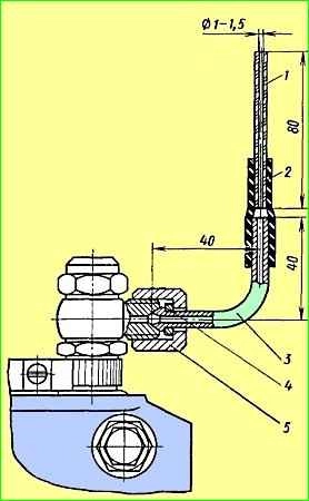
- - install a momentoscope on the fitting of the first section of the pump (see Fig. 5);
- - turn on the fuel supply with the regulator bracket;
- - pump fuel into the engine power supply system by unscrewing the handle of the manual booster pump and, moving it up and down, pump the system for 2-3 minutes. After pumping, screw the pump handle all the way;
- - rotate the engine crankshaft clockwise (as viewed from the fan side) using a wrench by the pulley mounting bolt or a crowbar by the holes in the flywheel until fuel appears in glass tube 1 (see Fig. 5).
Pour out excess fuel from the glass tube by shaking it with your finger;
- - turn the crankshaft counterclockwise approximately ⅛ turn. Then, slowly turning it clockwise, carefully monitor the fuel level in the glass tube.
The moment the fuel begins to move in the tube corresponds to the start of fuel supply by the 1st pump section.
With proper adjustment, at the moment the fuel begins to move, the mark on the crankshaft pulley 2 should be opposite the corresponding mark on the timing gear cover (Fig. 6) or a similar mark on the flywheel 2 should coincide with the pointer on the flywheel housing (Fig. 7).
If, at the moment the fuel begins to move in the tube, the marks have not yet aligned, it is necessary to unscrew the bolts and turn the coupling of the fuel pump drive shaft on the flange against the direction of its working rotation, then tighten the fastening bolts and check the injection timing again.</p >
The discrepancy between the marks should be no more than one division or 1 crankshaft rotation.
If, at the moment the fuel begins to move, the risk tube has already passed the combined position, the drive roller coupling must be turned in the direction of its operating rotation.
The displacement of the drive shaft coupling relative to its flange by one division corresponds to four divisions on the flywheel or timing gear cover.
After completing the advance angle adjustment, the coupling mounting bolts must be tightened.
If the engine is equipped with a high-pressure fuel pump drive of a new design with indicator 13 (Fig. 8), then the fuel injection advance angle is adjusted without a momentoscope as follows.
Align the marks shown in the figures; in this case, the mark “a” (Fig. 8) on the end of the coupling 12 must align with the risk oh "b" on the sign
If the marks “a” and “b” are not aligned, you need to unscrew the two nuts 7 and by turning the injection advance coupling, use the oval holes on the flange 6 of the coupling half to align the indicated marks.
Without disturbing the combined position of marks “a” and “b”, tighten the nuts of the 7 bolts and the flange of the coupling half and, turning the crankshaft, check that the injection advance angle is set correctly.