Installing cylinder heads, valve rocker arms and adjusting valve clearances
The cylinder head mounting studs are screwed into the right and left rows of the cylinder block, having previously lubricated the threaded holes for the studs in the block with diesel oil
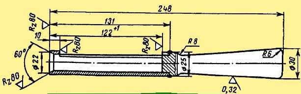
The studs are screwed in over the entire length of the thread with a torque of 80-100 Nm (8-10 kgcm); they should protrude above the plane of the block by 122 mm, which is checked with a bushing (Fig. 1).
Before installing the cylinder head, it is necessary to wipe the mating plane.
We install the cylinder head gasket on the studs so that it is installed on the pins, and the edging of the gasket is placed on the collars of the cylinder liners.
The cylinder head assembly must fit freely onto the studs and locating pins without impact.
Then we screw the cylinder head nuts onto the studs and tighten them.
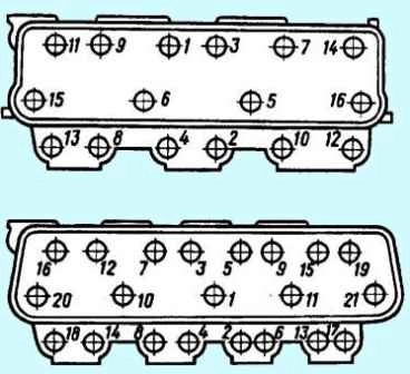
Tighten the nuts in ascending order of numbers (see Fig. 2).
After the first tightening with a torque wrench, it is necessary to re-check the required torque of 220-250 Nm (22-25 kgcm) on each nut, following the indicated sequence.
Push rods are installed in the windows of the cylinder block and at the same time the tip of the rod is aligned with the heel of the pusher.
The rod is first wiped and the tip is lubricated with diesel oil.
The right and left valve rocker arms with the axle assembly are installed so that the axle dowel pins fit into the holes in the cylinder head, and the sphere of the adjusting screw is aligned with the tip of the rod.
The adjusting screw must be screwed into the rocker until it stops.
Then screw the rocker arm axis mounting bolts into the cylinder heads and tighten them to a torque of 120-150 Nm (12-15 kgcm).

Valve clearances are adjusted simultaneously on two cylinders and a dial is used (Fig. 4).
The dial is installed on the crankshaft pulley, and pin 3 is inserted into the threaded hole on the timing gear cover.
Thermal clearances of the YaMZ-326 engine are adjusted in the following sequence:
- rotate the crankshaft clockwise with a wrench using the pulley mounting bolt, observe the movement of the intake valve of the first cylinder and set the moment when it is completely closed.
After this, the shaft is turned in the same direction until the marks on the crankshaft pulley align with the mark 1-4 YAM3-236 on the dial;
- adjust the gaps between the toes of the rocker arms and the ends of the valves of the first and fourth cylinders.
After tightening the lock nut of the adjusting screw, the 0.25 mm thick feeler gauge should fit freely into the 0.30 mm thick gaps - with force.
After turning the crankshaft, it is allowed to change the gap within 0.20 - 0.35 mm;
- combining on the compression stroke in the order of operation of the cylinders (1-4-2-5-3-6) the mark on the pulley with marks 1-4, 2-5, 3-6 YaMZ-236 on the dial, adjust the clearances for remaining cylinders.
When adjusting the thermal clearances of the YaMZ-238 engine, the same techniques and methods are used as for the YaMZ-236 engine:
- - combine figure 3 on the pulley on the compression stroke with mark 1-5 YaMZ-238 on the limb;
- - adjust the valve clearances of the first and fifth cylinders;
combining on the compression stroke in the order of operation of the cylinders (1-5-4-2-6-3-7-8) the mark on the pulley with marks 4-2, 6-3 and 7-8 YaMZ-238 on the dial, regulate the valves of the remaining cylinders.
The control valve pusher rods must rotate freely by hand.
The gap is adjusted using an adjusting screw; After adjustment, securely fasten the screw with a nut and check the gap.
Installation of injectors, fuel lines and connecting pipe.
A set of injectors of the same spray group is installed on the engine.
The spray group is applied to the surface of the nozzle body.
Before installing the nozzles, wipe the inner surface of the glasses, and put one sealing copper washer on the sprayer.
The injectors are installed so that the fitting seal fits into the recess of the cylinder head.
Injector mounting brackets are installed on the cylinder head studs, washers are put on and nuts are screwed in, which are tightened with a torque of 50-60 Nm (5-6 kgf m).
Drainage tubes are installed on the left and right cylinder heads, having previously removed the transport plugs from the injectors.
Drainage tubes are attached to the nozzles with connecting nuts and bolts, having previously placed washers under the tips of the tubes and under the heads of the bolts.
To ensure a reliable seal in all cases, it is necessary to orient the washers with the tops of the cones away from the tips of the tubes outward.
Fuel outlet lines are installed in the camber between the cylinders and bolted to the right and left cylinder heads.
To ensure a more rigid fastening, a clamp is installed on each fuel line and secured to the flange stud of the left intake pipe.
High pressure fuel lines are attached to the fittings of the high pressure fuel pump and injectors in a certain sequence corresponding to the operating order of the sections of the high pressure fuel pump.
The YaMZ-236 engine pump has an operating order corresponding to the operating order of the engine cylinders (1-4-2-5-3-6).
The order of operation of the pump sections of the YaMZ-238 engine differs from the order of operation of the cylinders of this engine.
If the operating order of the engine cylinders is 1-5-4-2-6-3-7-8, then the pump sections operate in the sequence 1-3-6-2-4-5-7-8.
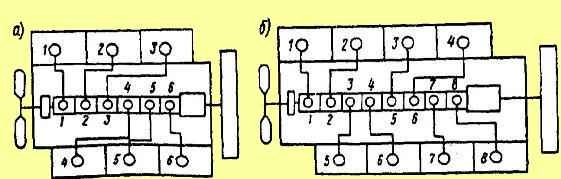
The connection diagrams of the pump sections with the cylinders of the YaMZ-236 and YaMZ-238 engines are shown in Fig. 5.
The connecting pipe of the intake pipelines is installed so that the flange for the compressor air duct is directed towards the front of the cylinder block.
The pipe is attached to the flanges of the inlet pipelines, having previously placed gaskets with assembled mesh and rubber gaskets on the flanges and secured with bolts and washers.
The oil dipstick is installed in the guide tube, having previously wiped it.
Then install the cylinder head covers, which are secured with screws on one or two threads and remove the engine from the stand.
Plugs are installed on the technological holes and secured with bolts.
It is necessary to install cardboard spacers under the plugs.
The running-in and testing of engines after repair is carried out on STE-160-1500 stands with electric brakes.
At these stands you can test YaMZ-236 and YaMZ-238 engines of all modifications.
Characteristics of electric brakes for test benches are given in the table
Electric brake AKB-104-4:
- - power 160 kW;
- - synchronous rotation speed 1500 min -1;
- - torque 1070 Nm (107 kgcm);
- - maximum engine crankshaft speed when operating in generator mode with rated torque - 3000 min -1
Electric brake AK-102-4:
- - power 160 kW;
- - synchronous rotation speed 1500 min -1;
- - torque 1100 Nm (110 kgcm);
- - maximum engine crankshaft speed when operating in generator mode with rated torque - 2500 min -1
The engine running-in and testing stand must have the equipment necessary to measure engine power, crankshaft speed, hourly fuel consumption, temperature of water leaving the engine (from the right and left water pipes), oil temperature in the engine sump, pressure oil in the line, fuel injection advance angle in degrees of crankshaft rotation angle.
Fuel consumption should be measured on scales with a measurement limit of up to 15 kg, time is counted using a stopwatch with a division value of 0.1 s; measurement of rotation speed - with a manual tachometer or tachoscope with a division value of no more than 10 minutes.
The capacity of the supply tank must be 10 - 12 l, the level of the bottom of the measuring tank must be at least 500 mm from the axis of the inlet of the fuel pump, the internal diameter of the inlet and outlet fuel lines must be at least 8 mm.
Fuel lines must not touch the measuring tank and must be immersed in fuel to a depth of no more than ⅓ of the height of the tank from its bottom.
At the submerged end of the fuel line that takes fuel away from the engine, a reflector is installed that prevents the direct direction of the jet flow to the bottom of the tank and helps equalize the temperature of the fuel in the tank.
The engine installed on the stand must be completely complete (with the exception of the fan impeller, generator, compressor).
The engine is run-in and tested using L grade diesel fuel.
During the running-in period, diesel oil is poured into the engine sump, fuel injection pump housing and regulator housing up to the upper marks of the oil level indicators.
The air filters are filled with diesel oil in the amount of 1.6 liters for the YaMZ-236 engine and 1.4 liters for the YaMZ-238 engine.
The oil temperature is maintained using technological oil radiators (at the beginning of the run-in not lower than 50˚ C).
The running-in and testing of the engine is carried out in special modes and includes cold and hot running-in, control acceptance.
Cold engine running
Before starting the stand, the crankshaft must be turned several times by hand to ensure that the engine is in good condition and that it is installed correctly on the stand, and to check and, if necessary, adjust the thermal clearances in the valve mechanism.
During the running-in process, the oil pressure in the system, the oil supply to the rocker arm bearings and the tightness of the injector seals in the cylinder heads are checked.
The stethoscope is used to listen for noises and knocks of timing gears, connecting rod and main bearings, piston pins and pistons.
If defects are detected, running-in must be stopped and continued after elimination.
The cold running mode is shown in the table.
At the end of the cold break-in, it is recommended to change the oil in the engine sump and wash the oil filters.
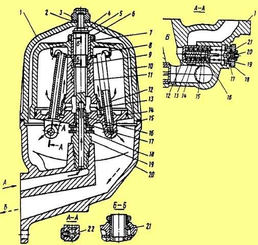
To wash the centrifugal filter rotor, unscrew nut 3 (see Fig. 6) of the filter cap, remove cap 1 and the rotor assembly.
The rotor is disassembled, sediment is removed from the cap 10 and rotor 11, and washed in diesel fuel.
The filter is assembled in the reverse order, checking the condition of the gasket 15, the cleanliness of the nozzle holes 22, the condition of the washer 2 and the position of the mesh 8.
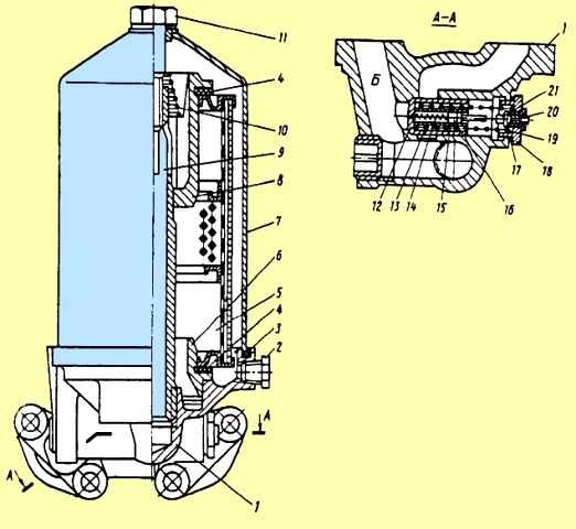
To wash the coarse oil filter, you need to drain the oil from the filter housing through the hole closed with plug 2 (see Fig. 7), unscrew the bolt 11 securing the Filter cap, remove the cap 7, the top cover 8 and the filter element 5.</ p>
The filter element removed from the engine is placed in a bath with a solvent (gasoline or carbon tetrachloride) for 3 hours.
After 3 hours, the element is washed with a soft hair brush, rinsed in clean gasoline or carbon tetrachloride and blown with compressed air.
During the washing period, technological replaceable filter elements are installed.
Engine cold running mode
Cold running mode of YaMZ-236, YaMZ-238, YaMZ-2Z8A, YaMZ-238G, YaMZ-238K engines
Crankshaft rotation speed, min -1 / engine running-in duration, min:
- 600 / 10;
- 800 / 10;
- 1000 / 5;
- 1500 / 5
- total / 40
Cold running mode of YaMZ-238I engines
- 600 / 10;
- 800 / 15;
- 1000 / 15;
- 1500 / -
- total / 40
Hot engine run-in
Before starting the engine, it is necessary to adjust the fuel injection advance angle.
To do this, check the relative position of the marks on the fuel injection advance clutch and the drive half of the fuel pump drive shaft coupling (the marks should be on one side);
- - remove the high pressure pipe of the first section of the injection pump;
- - a momentoscope is installed on the fitting of the first section of the pump.
After making sure that the regulator bracket is in the fuel supply on position, pump fuel into the engine power supply system with a manual booster pump for 2-3 minutes and rotate the engine crankshaft clockwise (as viewed from the fan) until fuel appears in the glass tube .
You can rotate the crankshaft using the bolt securing the crankshaft pulley or using a crowbar using the holes in the flywheel with the flywheel housing hatch cover removed.
Next, pour excess fuel out of the glass tube, shake it with your finger, turn the crankshaft counter-clockwise about 118 turns and, slowly turning the crankshaft clockwise, carefully monitor the fuel level in the glass tube.
At the moment the fuel level in the tube begins to move, stop the rotation of the shaft and check the relative position of the marks:
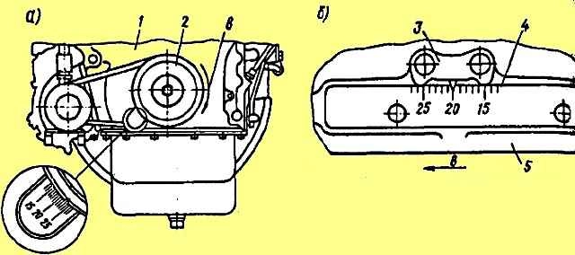
- the mark on the crankshaft pulley should be against the mark with the number 20 on the cover 1 of the timing gears (Fig. 8, a) or the mark with the number 20 on the flywheel 4 should coincide with the pointer 3 on the flywheel housing (Fig. 8, b) .
For the YaMZ-238K engine, the adjustment marks are combined with mark 14.
If, at the moment the fuel begins to move in the tube, the marks have not yet aligned, it is necessary to loosen the bolts, rotate the drive shaft coupling on its flange against the direction of its rotation, tighten the fastening bolts and check the injection timing again.
The discrepancy between the marks should be no more than one division.
If, at the moment the fuel begins to move, the risk tube has already passed the aligned position, the drive roller coupling must be turned in the direction of its rotation.
The displacement of the drive shaft coupling relative to its flange by one division corresponds to four divisions on the flywheel or timing gear cover.
After starting the engine, check the tightness of all connections of the engine fuel system.
The temperature of the water leaving the engine should be 75 – 95˚ C, while the difference in temperature of the water leaving the right and left pipes should not exceed 5˚ C.
It is recommended to maintain the temperature within the specified limits using a process radiator.
The oil pressure in the line at a temperature of 80 - 90˚ C should be 0.5 - 0.7 MPa (5 - 7 kgf/cm 2) at the rated crankshaft speed and not less than 0 .1 MPa (1 kgf/cm 2) at a rotation speed of 500 min -1.
The ejection and leakage of oil, water and fuel, as well as the breakthrough of gases at the joints are not allowed.
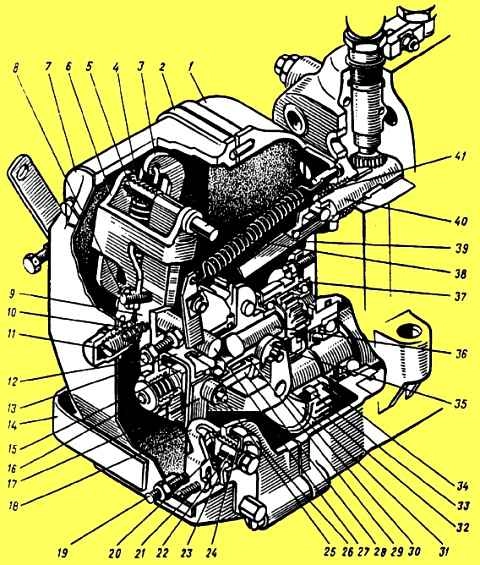
Camshaft speed regulator: 1 housing; 2, 7, 26 - covers; 3, 9, 17 - levers; 4 - Compensation spring; 5, 10, 23. 24, 38 – springs; 6 - double-arm lever; 8 - adjusting screw; 11 - buffer spring housing; 12 - adjusting bolt; 13 - earring; 14 - bracket; 15 - persistent heel; 16 - corrector; 18 - drawstring; 19 - power adjustment screw; 20 - clamp; 21 - rocker screw; 22- axis of the scenes; 25 - axis of the thrust heel; 27 - lever shaft; 28 - cargo coupling; 29 - ball; 30 - load; 31 - drive gear bushing flange; 32 - drive gear; 33 - cracker; 34 - bushing; 35- roller; 36 - weight holder roller, 37 - glass; 39 - traction; 40 - rail; 41 - lever axis
Signs of defects are not sweating, the formation of oil stains and individual drops in the places of the stuffing box seals, with no more than one drop falling within 5 minutes, under any engine operating mode;
- - light sweating without drop formation at connectors and connections;
- - release of oil and condensate through the outlet pipe of the crankcase ventilation system in an amount of no more than two drops per 1 minute at the rated crankshaft speed;
- - release of fuel through the drain pipe of the injectors in the form of drops, as well as a mixture of fuel and oil from the drain pipe of the injection pump housing;
- - release of water and lubricant from the drainage hole of the water pump is no more than one drop per 3 minutes, as well as drops of water when the engine is stopped;
- - slight sweating without oil dripping through micropores on the annular rib of the cylinder head.
It is allowed to release individual drops of the fuel-oil mixture from the exhaust pipe during the running-in period.
Hot running of engines is carried out in the modes given in the table
Go mode hot running-in of engines
At the end of the hot run-in, it is necessary to check and, if necessary, adjust the engine power.
The power of the YaMZ-236 engine at a crankshaft speed of 2050+15 min should be 178 -5 liters. With. with an hourly fuel consumption of 33 kg/h, the YaMZ-238 engine is 237-5 liters. With. at 44 kg/h, YaMZ-238A - 213-5 hp. at 39 kg/h, YaMZ-238G at a rotation speed of 1670 min -1 - 172-5 l. With. and hourly fuel consumption of 30.1 kg/h, YaMZ-238I - no less than 160 liters. With. at a rotation speed of 1500 min and 27 kg/h, YaMZ-238K - 190-5 hp. at a rotation speed of 2100 min -1 and hourly fuel consumption of 36 kg/h.
Hourly fuel consumption is determined by measuring the time of consumption of 500 g of diesel fuel three times.
The largest difference between repeated measurements should be no more than ±0.2 s relative to the average time value obtained as a result of all measurements.
The engine power is adjusted using the power adjustment screw 19 (see Fig. 9) at the crankshaft rotation speed indicated above for each engine and the governor control lever resting on the maximum speed limit bolt.
Smoothly reducing the load to zero, adjust the maximum idle speed:
- - for engines YaMZ-236, YaMZ-238, YaMZ-238A and YaMZ-238K - 2200-2275 min -1 ;
- - for the YaMZ-238G engine - 1850-1950 min1 ;
- - for the YaMZ-238I engine, the maximum crankshaft speed in idle mode should not exceed the rated speed by more than 100 minutes.
Checking the maximum rotation speed is carried out with the lever resting on the bolt for limiting the maximum speed mode and the buffer spring housing being turned out 10-11 mm from the end of the lock nut.
If the maximum crankshaft rotation speed in idling mode of the YaMZ-236, YaMZ-238, YaMZ-238A and YaMZ-238K engines is below 2225 min -1, determine the inflection point of the speed characteristic, which should lie in the range 2100 +50 min -1
The minimum crankshaft rotation speed in idle mode is adjusted within 450-550 min1, with the governor control lever resting on the bolt.
When screwing in a bolt, the frequency increases, when turning it out it decreases.
First, the rotation speed is gradually reduced until instability appears, and then the buffer spring housing is screwed in until the rotation speed increases by 10-20 minutes -1.
The engine must operate stably in idle mode with fluctuations of no more than 15 minutes -1.
Stability in this mode is checked by increasing the crankshaft rotation speed to 1200 - 1300 min -1 and sharply releasing the lever all the way to bolt 1.
For the YaMZ-238I engine, the amount of rotation speed instability (deviation from normal) is checked, which should not exceed ± 15 min -1 at 80 hp, 120 hp, and 150 hp.
After this, tighten the cylinder head nuts and, if necessary, adjust the valve clearances.
")

")
")
")
")
")
")
")