The clutch of the YaMZ-238 model is double-disc, dry, friction type, with a peripheral arrangement of cylindrical springs
The clutch housing 16 (Fig. 1), stamped from sheet steel, with the pressure disk 19 assembly is installed on the engine flywheel 20, and the driven disks 21 are installed on the splined part of the input shaft of the gearbox.
The front and rear driven discs are installed in a specific position, as shown in the figure.
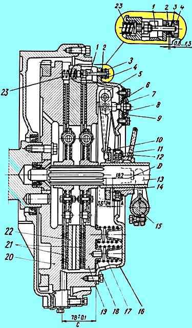
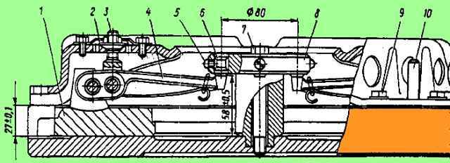
YAMZ-238 clutch: 1 - rod; 2 - ring; 3 - disc spring; 4 - bar; 5 - pull lever; 6 - pull lever fork; 7 - adjusting nut; 8 - support plate; 9 - locking plate; 10 - spring loop of the pull-out lever; 11 - clutch release clutch with bearing; 12 - lubricant supply hose to the clutch release clutch; 13 - clutch release fork; 14 - thrust ring of pull-out levers; 15 - clutch release fork shaft; 16 clutch cover; 17 - pressure spring; 18 - thermal insulating gasket; 19 - pressure disk; 20 - flywheel; 21 - driven disks; 22 - middle drive disk; 23 - release spring; D - minimum stroke of the release clutch
The driven clutch discs are clamped by a constant force of cylindrical pressure springs 17 between the engine flywheel, the middle and pressure discs.
Thermal insulating gaskets 18 are placed under the springs on the pressure disk side. The pressure and middle drive disks are connected to the flywheel by four tires located on the outer surface of the disks.
When clamped, the driven disks transmit engine torque to the gearbox input shaft.
The clutch is released using clutch 11.
The clutch with the bearing, moving towards the engine, removes the pressure disk from the driven disk, transmitting force through four rigid pull-out levers 5.
The working stroke of the clutch release clutch, taking into account free play, must be at least 18.2 mm (dimension “D”).
The amount of free play is regulated by the clutch release mechanism. The thrust ring of the retraction levers moves towards the gearbox by 27 mm due to the permissible wear of the friction linings.
Guaranteed clearances between the driven disks and the friction surfaces of the flywheel, middle drive and pressure disks when the clutch is disengaged as the linings wear are ensured by a mechanism for automatically adjusting the withdrawal of the middle disk
The mechanism consists of rods 1, fixed in each of the four studs of the middle drive disk, split rings 2, which require a certain force to move along the rod, thrust bars 4, which are bolted to the flywheel with the clutch housing, and disc springs 3, installed on the rod between ring 2 and bar 4.
When the clutch is disengaged, the pressure plate 19 moves back at least 2 mm and releases the rear driven disk 21.
The middle drive disk 22, under the action of the spring 23, also moves back, until the ring 2 stops in the bar 4 through a disc spring, by an amount of 1.2+0.1 mm, freeing the front driven disk.
As the clutch friction linings wear out, the middle drive disk moves to the flywheel under the action of the pressure springs, the rings 2 rest against the clutch housing, moving along the rods 1 and maintaining the size between the rings and the disc springs.
When the driven disc linings wear out, the end of the clutch release clutch will rest against the end of the gearbox input shaft bearing cover; in this case, replace the worn linings of the driven disks with new ones.
Installing the clutch on the engine
The clutch is installed on the engine in the following order:
- 1. install the front driven disk;
- 2. install the middle drive disk with rods;
- 3. install the rear driven disk;
Clutch driven discs can be installed: front 238-1601130-B, rear 238-160113 1 (not interchangeable); or two disks 238-1601 130-G2 (interchangeable).
Two disks 238-1601130-G2 can be installed instead of the front disks 238-1601130-B and rear 238-160113 1. And vice versa.
The end of the extended part of the disk hub 238-1601130-G2 is marked 238-1601130-G2.
When installing them, the following conditions must be met:
- - disk to the flywheel - marked side of the hub to the engine;
- - disc to pressure plate - marked side of the hub to the gearbox.
- 4. install the pressure plate with housing assembly, securing it to the flywheel using eight short bolts;
- 5. put the split rings 2 on the rods 1 until they stop in the clutch casing;
- 6. wear four. disc springs with the convex side to the split rings:
- 7. install four stop bars and secure them with the casing to the flywheel using eight long bolts.
After installing the clutch on the flywheel, make sure that the rings on the rods rest against the housing, providing a gap of 1.2+0.1 mm between the rings and the disc springs when the clutch is engaged.
Adjust the clutch free play.
Attention! Lack of free play of the clutch release clutch will lead to failure of the pressure bearing and slipping of the discs.
After adjustments, check the clutch for absence of “driving”. Carry out this check with the engine running, first gear engaged and the clutch disengaged.
Adjusting the position of the thrust ring of the pull-out levers
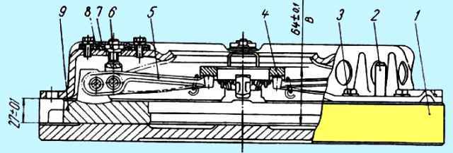
Device for assembling the pressure disk with the casing assembly: 1 - stand; 2 - guide pin; 3 - casing mounting bolt; 4 - thrust ring of pull-out levers; 5 - pull lever; 6 - adjusting nut; 7- locking plate; 8 - support plate; 9 - pressure disk
When assembling the pressure plate with the housing assembly, adjust the position of the thrust ring.
This adjustment is made in a device having an installation size of 27 ± 0.1 mm (Fig. 2) with adjusting nuts 6 pull-out levers with the casing and pressure plate in a fixed position.
By adjusting, ensure dimension “B” is equal to 64±0.1 mm, while the thrust surfaces of all four pull-out levers 5 must simultaneously touch the thrust ring 4.
The skew of the thrust ring will lead to uneven release of the pressure plate when the clutch is disengaged or its abnormal operation.
After adjusting the position of the thrust ring using the adjusting nuts 6, install the locking 7 and support 8 plates of the adjusting nuts.
Tighten all eight bolts securing the locking and support plates, installing spring washers under the bolt heads.
In the case of using a pressure plate with a casing complete with driven disks after repair, on which friction linings 4.15 mm thick are installed, when adjusting the position of the thrust ring, set dimension “B” to 67+0.1 mm.
Clutch maintenance
Maintenance of the clutch is carried out similarly to the maintenance of the YaMZ-182 clutch (see above) with the addition:
Check each TO-1 and, if necessary, adjust the free play of the clutch release.
The free play of the clutch release clutch, determined by the gap between the thrust ring and the clutch bearing (dimension “A” in Fig. 1. 3.2-4.0 mm), is achieved by adjusting the clutch release mechanism in accordance with the instructions in the vehicle operating instructions.
After adjustments, check the clutch for absence of “driving”. Carry out this check with the engine running, first gear engaged and the clutch disengaged.
Adjusting the free play of the clutch release clutch using the adjusting nuts of the release levers is strictly prohibited.
Torsional vibration damping and power take-off mechanism
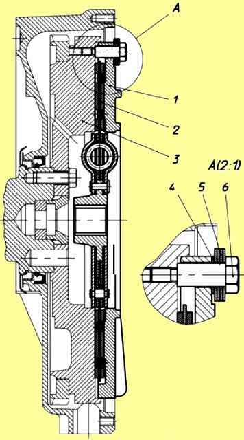
Mechanism for damping torsional vibrations and power take-off: 1 - clamping flange; 2 - driven disk; 3 - flywheel; 4 - spacer washer; 5 - package of disc springs; 6 - stepped bolt.
Power units can be equipped with a mechanism for damping torsional vibrations and power take-off (Fig. 3), designed to dampen resonant torsional vibrations and protect transmission systems from destruction.
The mechanism is installed on the engine flywheel and consists of a pressure flange 1, a driven disk 2 with friction linings and a mechanism for damping torsional vibrations, packages of disc springs 5 and stepped bolts 6.
Driven disk 2 is constantly pressed to flywheel 3 through flange 1 by packages of disc springs 5 assembled on stepped bolts 6.
The step bolts are screwed into the flywheel until they stop. When installing stepped bolts, sealant UG-6 TU 6-01-1285-84 is applied to their threaded part and tightened with a force of 49-59 Nm (5-6 kgcm).
The number of packages of disc springs and bolts is selected so that the friction moment they create allows the transmission of torque from the flywheel to the power take-off shaft up to 1700 Nm (170 kgcm).
When the driven disk is loaded with a torque of more than 1700 Nm (170 kgcm), the force of the springs is not enough to hold the driven disk and it rotates relative to the flywheel and thereby protects further kinematic connection from destruction.
During operation, the mechanism does not require maintenance.
Malfunctions of the driven disk that are possible during operation are similar to malfunctions of the clutch driven disk.
Premature slipping of the driven disk can be eliminated by installing additional packages of disc springs together with the bolt and further checking the friction torque in the following order:
- 1. Lock the engine flywheel.
- 2. Load the driven disk of the mechanism with a torque of less than 1700 Nm (170 kgcm). the disk should not rotate relative to the flywheel.
- 3. Load the driven disk of the mechanism with a torque of 1700-1900 Nm (170-190 kgcm). The disk must rotate relative to the flywheel.
Clutch repair
Clutch repair consists of disassembling the pressure plate set 22 (see Fig. 1) with release levers and clutch housing 19 assembled.
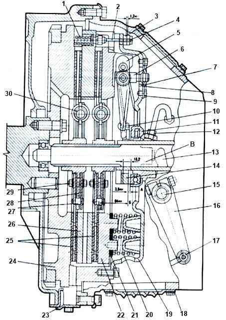
1 - release spring; 2 - rod; 3 - ring; 4 - thrust bar; 5 - pull lever; 6 - fork; 7 - adjusting nut; 8 - support plate; 9 - locking plate; 10 - spring loop of the pull-out lever; 11 - clutch release clutch; 12 - lubricant supply hose; 13 - clutch release fork; 14 - thrust ring; 15 - clutch release fork shaft; 16 - fork shaft lever; 17 - finger; 18 - hatch cover; 19 - clutch casing; 20 - pressure spring; 21 - thermal insulation gasket; 22 - pressure disk; 23 - flywheel housing hatch cover; 24 - flywheel; 25 - driven disks; 26 - middle drive disk; 27 - thrust pin; 28 - hub; 29 - coupling bolt; 30 - damper spring; A - gap between the thrust ring and the clutch release clutch; B - control size; B - clutch stroke
Complete disassembly of the clutch pressure plate assembly is carried out only to replace or repair its parts, the need for which is determined by failures in operation or during external inspection.
Before disassembling the clutch, marks should be made on the pressure plate 22 and on the casing 19 to ensure the correct relative position of these parts during assembly and thereby maintain the original factory balancing of the clutch.
Disassembly of the pressure set is carried out in a device (Fig. 4) or on a wooden stand under a hand press in the following order:
- place pressure disk 1 assembled with the casing on fixture 1 with disk down and secure with four tenons in the grooves.
Pressing on the end of the casing 19 (see Fig. 4), compress the springs 20 so that the pull-out levers 5 with the thrust ring 14 are in a free state, bend the locking bars and unscrew all eight bolts securing the support plates of the adjusting nuts.
Remove the support plates 8 from the adjusting nuts 7, the locking plates 9, unscrew the four adjusting nuts 7 (see Fig. 1) of the retraction arms and slowly lower the clutch cover;
- remove the clutch cover, remove the pressure springs 20 from the pressure plate bosses 22, thermally insulating gaskets 21 with washers, release the hinges 10 of the tension lever springs and remove the thrust ring 4, the lock washers of the axles on which the tension levers are mounted in special eyes of the pressure disk , and carefully remove the axles and rollers of the needle bearings.
After this, disassemble the pull-out levers 5, for which you need to remove the lock washers, remove the axes of the lever forks and the rollers of the needle bearings.
When checking the technical condition of the clutch pressure plate, you should pay special attention to the condition of the working friction surface.
If on this surface burn spots and a network of cracks with a crack width of more than 0.2 mm cover more than 40% of the entire surface, or the warpage of the disk, measured with a probe on the plate, is more than 0.5 mm, the disk should be restored or replaced.
The working surface of the pressure disk is corrected (to a roughness of 2.5 microns) by grinding or grooving with thorough cleaning with fine emery cloth.
After processing, the surface should be flat and when checking on the plate, a probe with a thickness of 0.07 mm should not pass through.
If the defects are not eliminated by grinding the disk to an acceptable thickness, the disk should be replaced with a new one.
When inspecting the clutch driven disc, you should pay attention to the condition of the surface of the friction linings and the strength of their fastening with rivets.
Breakage of the linings and oiling of the working surfaces of the linings are not allowed.
Radial cracks of the linings near the rivets are allowed without them extending to the edge or into another hole for the rivet.
Clutch friction linings can wear down to 1.2 mm rivets on each side.
To remove worn, damaged friction linings, you need to drill out the riveted holes of the rivets securing the linings from the drilling side and knock them out with a beard.
After riveting the new linings, the driven disk must be checked for runout of the friction planes relative to the splined axis th hole of the hub.
To do this, the driven disk is mounted on a splined mandrel and secured in the centers of the fixture or lathe.
The drive shaft of the gearbox can be used as a mandrel.
The runout of the working surfaces relative to the axis of the hub spline hole at a radius of 175 mm should not exceed 0.7 mm. To eliminate disc runout, it can be edited.
The thickness of the driven disk with riveted linings should be (10±0.1) mm. The difference in thickness of the linings for one driven disk should not exceed 0.3 mm.
Device for assembling and disassembling the pressure plate with housing assembly: 1 - clutch pressure plate with housing assembly; 2 - support plate; 3 - adjusting nut; 4 - clutch release lever; 5 - screw for fastening the cracker; 6 - persistent cracker; 7 - fastening bolt; 8 - mandrel for adjusting the position of the pull levers; 9 - clutch housing fastening bolt; 10 - guide pin; 11 - device stand
Assembly of the pressure set should be done in the fixture shown in Fig. 4 and under hand press.
The device consists of a stand having an installation dimension from the mating plane of the clutch casing to the plane of the pressure plate (27±0.1) mm.
In the center of the stand, a mandrel 8 is attached with a bolt 7 to adjust the control size of the pressure set B (see Fig. 3), equal to (64 ± 0.5) mm. The mandrel contains four floating thrust blocks 6 (see Fig. 5).
When installing the pressure set into the fixture, the crackers rest against the legs of the pull levers 4 and, depending on their position, protrude or sink relative to the surface of the mandrel.
The length of the mandrel is chosen in such a way that when installed on the pull-out levers of the pressure set with the control size correctly adjusted, the crackers are flush with the surface of the mandrel.
The control size (64+0.5) mm of the clutch push kit also includes the thickness of the thrust ring of the release levers, which is (6±0.1) mm; and since the pressure set is adjusted in a fixture without a stop ring, it must be adjusted to a size reduced by this amount, i.e. (580.5) mm.
Assembly and adjustment are carried out in the following sequence: a pressure disk is placed on the stand 11 of the device with the working surface down, fixed with four pins in the grooves of the stand, a needle bearing is inserted into the pull-out levers 4 (20 needles in each hole).
The needles are placed on cyatim-201 lubricant or another corresponding grease.
Forks 6 are installed on the pull-out levers (see Fig. 1), the fork axles are inserted, the assembled levers are installed in the grooves of the pressure plate lugs, the lever axes are inserted, the thrust ring springs are put on the fork axles, the lever and fork axes are secured with special lock washers , bending the middle of the apron jumper.
Then four loops 10 are put on the ends of the springs of the thrust ring 14, pressure springs 20 are placed on the bosses of the pressure disk, having previously placed washers with thermally insulating gaskets 21 under them.
When using a pressure disk machined 1 mm along the working surface, a 1 mm thick steel washer is placed under each pressure spring 20 (from the side of the casing guide cups) to maintain the clutch pressure.
Next you need to place the clutch housing 19 on the guide pins of the device. All guide cups of the casing must fit into the pressure springs, and the threaded shanks of the forks of the pull-out levers into the holes of the casing.
Using a press, it is necessary to press the casing with the mating surface against the device and secure it with bolts, then release it from under the press.
Screw the adjusting nuts 3 onto the threaded shanks of the forks, install a mandrel to adjust the position of the pull-out levers 4 and secure it with bolt 7 (see Fig. 5).
After this, adjusting nuts 3 adjust the position of the pull-out levers 4 so that they all simultaneously touch the thrust blocks 16 of the mandrel 8, which must be flush with its upper surface.
This ensures a control size between the working surfaces of the pressure plate and the thrust ring when installing the thrust ring.
Plates 2 are placed on the adjusting nuts 3, then the locking strips and the support plates of the lever forks, after which all eight locking bolts are screwed in.
After tightening the bolts, the forks of the release arms should not have any axial play. The bolts are secured by bending the locking strips.
Having installed a thrust ring on the pull-out levers, secure it with loops so that it simultaneously touches the supporting surfaces of all four levers.
Runout of the end of the thrust ring relative but the working surface of the pressure plate should not exceed 0.4 mm at a radius of 45 mm.
Increased runout of these surfaces can lead to failure of the friction linings of the clutch driven disc and burns to the working surfaces of the flywheel and pressure plate.
")

")
")
")
")
")
")
")