The switch type VK 860B is designed to connect the storage batteries to the vehicle ground and disconnect them
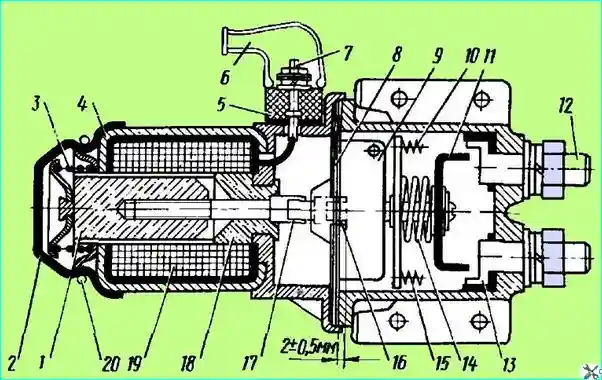
The design of the switch is shown in Fig. 1.
The switch is designed for an operating current of up to 1000 A.
The minimum tripping voltage of the switch is not less than 20 V.
The rated operating current of the electromagnet is 8.14 A.

Fig. Battery mass switch: 1 - electromagnet anchor; 2 - anchor protective cover; 3 - anchor spring; 4 - electromagnet housing; 5 - contact block; 6 - protective cover; 7 - wire connection terminals; 8 - gaskets; 9 - locking device mechanism; 10, 15 - moving contact springs; 11 - moving contact; 12, 13 - fixed contacts; 14 - moving contact pressure spring; 16 - armature rod in position with switch on; 17 - armature rod in position with switch off; 18 - electromagnet core; 19 - electromagnet winding; 20 - retaining ring
Voltage from the button is applied to the electric winding 19.
The anchor 1 is drawn into the solenoid and with the rod 17 presses the mechanism 9 of the locking device, through which it acts on the rod of the movable contact and closes it with the fixed contacts.
The mechanism 9 holds the contact 11 in the on state even after the voltage is removed from the winding 19 (the button is off).
When the button is pressed again (voltage is applied to the solenoid), the rod 17 acts on the mechanism 9, which releases the rod.
The movable contact 11, due to springs 10 and 15 (not shown in full in the figure), returns to its original position, opening the main contacts.
In the event of failure of the electrical part of the switch, the latter has manual control. By pressing the cover 2, you can turn the switch on or off.
During operation, ensure that the protective covers 6 are securely placed on the terminals 7, protecting them from contamination.
At the same time, ensure that the drives are securely connected to the fixed contacts.
When disassembling the switch to clean the contacts, do not disturb the position of the rod 17 screwed into the anchor along the thread.
If the rod is accidentally unscrewed from the anchor or screwed into it, its position must be adjusted.
If the rod position is not adjusted, the switch will not be fixed in the on position.
To adjust, screw the rod into the anchor so that its surface, when the anchor is pushed into the solenoid, protrudes above the surface of the gaskets 8 by 2 ± 0.5 mm, as shown in Fig. 1 (rod position 16).


