Disassembling the cylinder block
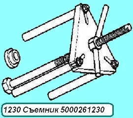
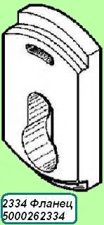
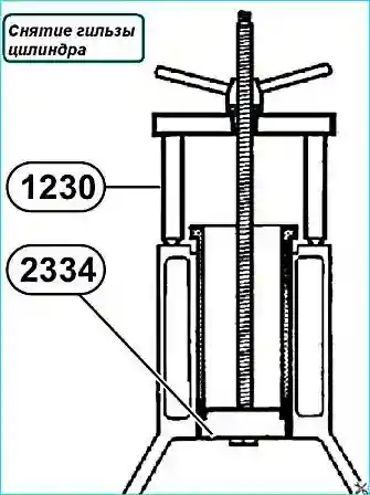
Remove the liners (650.1002021) using tools 1230 + 2334 (see Fig. 1)
Remove the sealing rings (650.1002031).
Remove the sealing rings of the cylinder liners (1002023, 1002024).
Unscrew the fitting for the oil pressure sensor (650.1002600).
Flushing the cylinder block
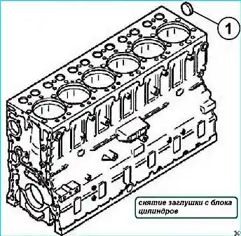
- 1. If necessary, remove the plug (1) (see Fig. 2).
- 2. Thoroughly clean all cylinder block channels
Cylinder block inspection
- 1. Check the bearing surface for the cylinder head gasket.
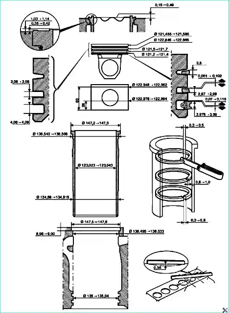
- 2. Check the ovality, taper and dimensions of the liners (see Fig. 3).
Assembling the cylinder block
1. Install the cylinder liner sealing rings in the grooves of the lower block seat belt (oil ring (650.1002024) - green, water ring (650.1002023) - black).
The sealing rings must be replaced each time the cylinder liners are dismantled.
- 2. Install sealing rings under the liner flange.
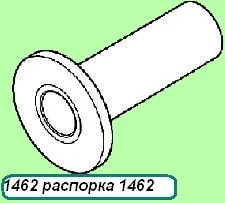
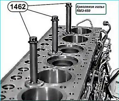
- 3. Install cylinder liners and secure them using fixtures 1462 (see Fig. 4).
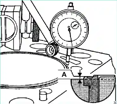
4. Check the protrusion of the liners (see Fig. 5).

Observe dimension “A” (see Fig. 6).

- 5. Apply “Loctite 542” sealant to the seating surface of the plug.
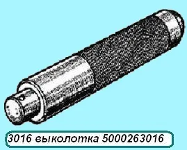
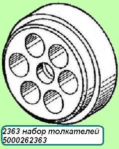
- 6. Install the plug (1) (see Fig. 7) using the 3016 + 2363 Ø55 mm tool (see Fig. 9).
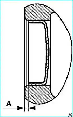
- 7. Check for the presence of an indent (“A” = 2 ± 0.5 mm) (see Fig. 8).
- 8. Install the oil pressure sensor nipple together with the gasket and tighten Mkr = 40 ± 4 Nm.
- 9. Apply “Loctite 542” sealant to the thread of the oil pressure sensor (650.1130552) and screw it into the nipple Mkr = 20 ± 4 Nm
Tools for disassembling and assembling the cylinder block
