Removing the steering gear from the car
To remove the steering gear from the car, do the following:
- — set the front wheels straight;
- — disconnect the steering column cardan shaft fork from the input shaft by unscrewing the clamping bolt;
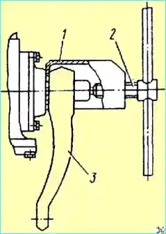
Fig. Removing the steering knuckle: 1 - puller body; 2 - screw; 3 - pitman arm
- — remove the cotter pin and unscrew the pitman arm mounting nut on the shaft and remove the pitman arm from the shaft using a special puller (Fig. 1), without disconnecting the longitudinal rod from the pitman arm as follows:
- — remove the cotter pin and unscrew the sector shaft nut. Install the puller so that the gripping flange of the puller body 1 is located between the steering gear housing and the pitman arm. Remove the steering arm 3 by turning screw 2 with a ratchet.
- — disconnect the hoses from the distributor, having first drained the oil from the tank and the steering gear housing;
- — unscrew the bolts securing the steering gear to the frame bracket and remove the steering gear.
Disassemble the steering gear in the following sequence:
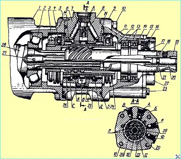
Fig. Power steering distributor: 1 steering gear housing; 2, 4, 11, 13 — bearings; 3 — nut; 5 — sealing ring; 6 — distributor housing; 7 — check valve; 8 — ball; 9 — distributor cover; 10, 23 — bolts; 12 — bushing; 14 — adjusting gaskets; 15 — cuff; 16 — retaining ring; 17 — ring; 18 — input shaft; 19 — pin; 20 - torsion bar; 21 — sealing ring; 22 — gland cover; 24 adjusting gasket; 25 — plunger; 26 - spool valve; 27 - pin. 28 screw; A — channel for draining working fluid to drain; 11 — channel for supplying working fluid from the pump; k, g — channels for supplying (discharging) working fluid to the cavities of the power cylinder; C, E, D - annular bores; M. No. - drillings for connecting the cavities of the thrust bearings with the drain; and — gap
- — remove the distributor, having previously marked the relative positions of the housing 1 of the steering gear (see Fig. 2), the housing 6 of the distributor, and the cover 9 of the distributor.
It is recommended to remove the distributor using a simple device.
To do this, unscrew the bolts 10 of the distributor and the two opposite bolts 23, with which you secure the base of the device to the cover 22 of the oil seal, rest the screw of the device through the ball in the torsion bar so that the pin 19 passes freely together with the input shaft 18, and then, screwing in the screw of the device, remove the distributor.
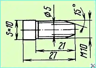
fig. Bolt for removing the distributor
If there is no device, the distributor can be removed as follows - unscrew bolts 10, turn housing 6 of the distributor so that the holes in it do not coincide with the holes in housing 1 of the steering gear and, screwing two special bolts (Fig. 3) into housing 1 of the steering gear (see Fig. 2), remove the distributor;
- - disconnect cover 9 of the distributor assembled with input shaft 18 from housing 6 of the distributor assembled with spool valve 26 and sleeve 12, having previously marked the position of the groove on sleeve 12, into which the flange of nut 3 is punched, relative to input shaft 18;
- - knock pin 19 out of input shaft 18 and clean the circular grooves of the shaft to the torsion bar;
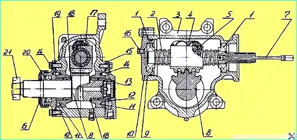
Fig. Steering gear: 1 adjusting linings; 2 - screw; 3 - rack nut; 4 - housing; 5 - distributor: 6 channel; 7 sector; 8,15 - eccentric bearings; 9 - pin; 10, 16, 28 - cover; 11, 29 - bearings; 12 hole 13 pressure limiting valve 14 - annular bore; 17, 27 - side face; 18, 26 - roller; 19, 25 - lever; 20 - rod; 21 - nut; 22 - cork; 23 - housing 24 - lock nut
- — turn screw 2 (see Fig. 4) to move the rack nut to one of the extreme positions;
- - unscrew the bolts and remove the side covers 15 to 19, remove the liners 12 and the toothed sector 8 from the housing;
- — unscrew the bolts and remove the cover 10, remove screw 2 with rack nut 4 from the housing.
By visual inspection, check the condition of the rack nut and sector teeth, the raceways of the screw and rack nut, the condition of the bearings, balls and their guides.
The presence of small pits (pitting) on the teeth of the sector and rack nut, on the balls or on the raceways of the screw, rack nut and bearings rolling indication indicates the beginning of wear of these parts.
In this case, it is better to replace the parts, since wear will progress.
When replacing worn parts, keep in mind that the screw, rack nut and balls can only be replaced as a set.
Check the condition of the thread on the input shaft, the thread and splines of the valve sleeve, the splines of the screw and plain bearings, which should not have any signs of scoring.
There should also be no gap in the connection of the torsion bar with the screw.
Only the crankcase, side and lower covers in the steering gear are subject to restoration when the bearing seats are worn by installing repair bushings.
The remaining parts of the steering gear are subject to replacement if there is visible damage and wear.
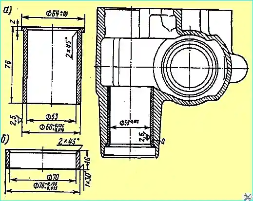
Fig. Steering gear housing repair bushings: a - for steering sector needle bearings; b - under the outer ring of the propeller bearing
The steering gear housing made of malleable cast iron is subject to restoration if the diameter of the hole for the needle bearings of the toothed sector of the steering sector of the steering gear is more than 55.05 mm by installing a repair sleeve (Fig. 5, a).
To do this, the housing is installed on the faceplate of the lathe with the plane under the side cover, the hole for the repair sleeve is bored to 60 +0.06 mm and the socket for the flange of the repair sleeve to a diameter of 64 +0.1 mm to a depth of 14 mm from the end of the neck.
Then press the sleeve into the bored hole until it stops against the flange, ensuring an interference fit within 0.05 - 0.075 mm, and bore the hole in the sleeve to a nominal diameter of 55 +0.013 mm.
If the hole for the outer ring of the propeller bearing is worn to a diameter of more than 72.04 mm, it is restored by installing a repair sleeve (Fig. 5, b).
To do this, bore the hole to a diameter of 76+0.06 mm, without violating the size of 203+0.2 mm from the end of the crankcase from the side of the lower cover to the end of the bore of the hole.
Press in the repair sleeve until it stops with an interference fit within 0.05 - 0.075 mm and bore the hole in it to a nominal diameter of 72 +0.02 mm.
The axes of the holes for the ring of the upper bearing of the steering gear propeller and for the needle bearings of the gear sector must be mutually perpendicular with an accuracy of 0.03 mm per 100 mm.
Surfaces holes for the upper bearing ring of the steering screw and for the lower cover must be concentric, the permissible runout is 0.02 mm.
The side cover of the crankcase, made of malleable cast iron KCh 37 - 12, is subject to restoration if the thread for the adjusting screw is damaged and is rejected if the seating surfaces are broken, cracked and worn.
If the M12 x 1.25 thread for the adjusting screw is damaged, the cover is restored by installing an insert, for which the hole with the damaged thread is drilled to Ø 13.7 + 0.2 mm, an M16 thread is cut with a tap and the insert is screwed in.
Then a hole of Ø 2 mm is drilled to a depth of 6 mm at the threaded connection of the insert and the cover, a pin is pressed flush into the hole and the M12 x 1.25 thread is calibrated in inserted.
The lower crankcase cover, made of malleable cast iron KCh 37-12, is subject to restoration only if the hole for the outer ring of the bearing is worn. In case of other defects of the cover, it is rejected.
A worn hole for the outer ring of the bearing more than 72.04 mm is restored by installing a repair sleeve.
The cover is installed with the landing neck on a lathe and the hole is bored to a diameter of 76+0.06 mm to a depth of 16 mm.
Then a sleeve with an internal diameter of 70 mm and a height of 16 mm is pressed into the bored hole, the hole in it is bored to a diameter of 72.2 mm and a chamfer of 1x45° is removed.
The steering gear is assembled in the reverse order of disassembly. Particular attention is paid to the installation of bearings and seals. These works are performed using special mandrels.
Assembling the steering gear
The assembly sequence is as follows:
- — adjust the tension in bearings 13 (see Fig. 2) using adjusting linings 14. The torque required to turn input shaft 18 in the cover should be within 0.58 Nm;
- — adjust the tension in bearings 4 and 11 using nut 3. The torque for turning sleeve 12 in the bearings should be within 0.02—0.04 Nm.
In this case, body 6 with the spool valve should move under its own weight relative to sleeve 12 in the radial direction by the amount of the gap between sleeve 12 and valve.
After adjustment, screw the flange of nut 3 into the groove of the sleeve:
- — connect sleeve 12 by thread with input shaft 18 according to the marks applied during disassembly. The splines on the sleeve must match the internal splines of input shaft 18;
- — install screw 2 (see Fig. 4) with a rack nut and bearings and into housing 3. Using adjusting linings 9, adjust the tension in the bearings.
The torque required to turn screw 2 until the rack nut stops in housing 3 should be within 0.9-1.5 Nm.
Repeat the torque determination operation several times with a preliminary turn of the screw in the rack nut (within one revolution);
- — set the rack nut by turning the screw to the middle position;
- — install the sector with thrust rings 18 in housing 3 so that the middle tooth of the sector falls into the middle recess of the rack nut;
- — install liners 12 on both sides of the sector shaft. The marks on the ends of the bushings should be on the side opposite the rack nut;
- — adjust the engagement of the rack nut with the sector (see the subsection "Adjusting the steering gear") so that the torque required to turn the screw (without the distributor) in the middle position is within 2.9-3.9 Nm;
- — install the distributor in the steering gear housing according to the marks made during disassembly. In this case, the circular grooves in the torsion bar 20 (see Fig. 2) and on the input shaft 18 must match;
- — install the pin 19 and lock it by punching into the end of the input shaft 18. The pin must enter the hole with a slight interference fit.
When replacing parts of the distributor or the steering gear housing (except for the cover 22 of the seal and the cuff 15), it is necessary to set the spool valve to the neutral position after assembly, for which:
- — install the steering gear on a stand equipped with a pump and a pressure gauge;
- — lock the sector shaft and plug channels "K" and "G" with plugs for connection with the cavities of the cylinder; connect channel “B” to the pump, and channel “A” to the drain;
- — with the pump running, turn the input shaft 18 to find the position at which the pressure in the system will be minimal; screw the bolt into the radial hole of the input shaft 18 and lock the torsion relative to the shaft.
With the torsion locked, the spool should clearly return to the neutral position when the torque is removed from the input shaft 18;
- — if the circular grooves on the torsion and shaft do not match, drill a hole of a larger diameter and install a new pin 19.
The torque required to turn the steering gear screw with the distributor in the middle position of the rack nut should be within 2.7-4.1 Nm.
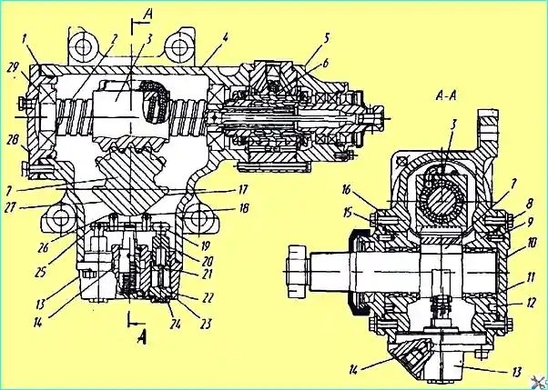
Steering gear: 1 - adjusting shims; 2 - screw; 3 - rack nut; 4 - housing; 5 - distributor: 6 - channel; 7 - sector; 8,15 - eccentric bearings; 9 - pin; 10, 16, 28 - cover; 11, 29 - bearings; 12 - hole 13 - pressure limiting valve 14 - annular bore; 17, 27 - side face; 18, 26 - roller; 19, 25 - lever; 20 - rod; 21 - nut; 22 - plug; 23 - housing 24 - lock nut
Steering gear disassembly (Fig. 6) is similar to steering gear (Fig. 4), only before removing sector 7 with liners 8, 15 from housing 4, it is necessary to first disconnect the bypass tube and pressure limiting valve 13 in order to avoid damaging it.
Steering gear assembly (Fig. 6) is similar to steering gear (Fig. 4), only before installing the distributor in the steering gear housing:
- — fasten side covers 10 and 16, then install pressure limiting valve 13 and bypass tube connecting channel 6 for supplying oil to distributor 5 and annular bore 14 of pressure limiting valve 13.
Steering gear installation on vehicle
Installation procedure next:
- — fasten the steering gear to the frame bracket;
- - by turning the input shaft 18 (Fig. 2), align the mark on the end of the sector shaft with the mark on the pitman arm, put the pitman arm on the splines of the sector shaft and fasten it;
- — connect the fork of the steering column cardan shaft to the input shaft 18, having first installed the key, and screw the tie bolt into the fork;
- — connect the hoses to the distributor and fill the system with oil.


