ABS control diagnostics f. Wabco car MAZ
Entering into diagnostic mode
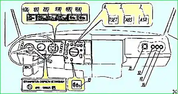
The electronic unit is turned on in the diagnostic mode by pressing the diagnostic button 12 (Fig. ) and holding it on for 0.5 to 3.0 seconds, with the ground switch and the starter and instrument switches on ( the lock must be in the “instrument” position)
The ABS lamp should light while holding the button.
At the same time, if the lamp was on before entering the diagnostic mode (which indicates the presence of active errors), then when you press the button it goes out for about 1 second, and then a cyclically repeating active error code is issued every 4 seconds. until this problem is resolved*.
If there are several active errors in the system, then after the first error is eliminated, a light code for the second active error will be displayed, etc. (until all faults are eliminated).
After eliminating all active errors, you must turn off and turn on the starter and instruments switch to the “instruments” position.
If there are no active errors, then in the diagnostic mode, light codes of the last 4 passive or “floating” errors are displayed sequentially (every 4 seconds), that is, errors that existed, but are absent at the time of diagnosis (or remain erased in the block memory) - information about passive errors is displayed 1 time.
To re-display the passive error light code, you must press the diagnostic button again.
Determining the cause of a malfunction using a flashing light code
The flashing light code about the nature of the malfunction and the faulty system element consists of two information blocks, which are two sequences of light flashes.
The duration of each flash is 0.5 seconds, the pause between flashes is 0.5 seconds, between blocks is 1.5 seconds.
The faulty component and the nature of the fault are determined by the number of flashes of the red ABS warning lamp in the first and second blocks, respectively, according to Table 1.
If there are no failures or malfunctions, a light code 1-1 is issued (one flash of the warning lamp in each information block).
*An active error is an error or malfunction that is present at the moment, i.e. at the time of diagnosis
Light codes for the status of ABS elements f. Wabco
System control mode
In system mode, the system configuration can be determined, the last four (passive) errors from the electronic unit memory can be erased, the system can be reconfigured and the engine control drive can be tested (for speed limit mode).
To activate the system mode, you must press the diagnostic button (figure) and hold it on from 3.0 to 6 .3 sec.*
After activating the system mode, a light configuration number is issued (MAZ vehicles have a 4S/4K sensor/4 modulator type system installed), the number of lamp flashes should be equal to 2.
The configuration code is repeated every 4 seconds.
To exit the system mode, you must turn off and turn on the starter and instruments switch to the “instruments” position, or press the diagnostic button for a time exceeding 6 seconds.
Erasing errors
Only passive errors stored in the memory of the electronic unit are erased.
To erase errors, you must activate the system mode, as described above. This will be followed by eight rapid (0.1 second duration) flashes of the ABS warning light, confirming the erasure.
The following is a configuration code repeated periodically every 4 seconds (two light flashes lasting 0.5 seconds with a pause of 1.5 seconds).
Then you need to turn off and turn on the switch for the starter and instruments to the “instruments” position.
Exit diagnostic mode
Exiting diagnostic mode is disabled Power supply (starter switch and instruments switched to the “off” position).
To exit the diagnostic mode without turning the lock to the “off” position, you must press the diagnostic button for a period of 6 to 15 seconds. In this case, the output of light codes to the red ABS indicator lamp stops.
If erasing a fault code is difficult (after repeated erasing operations the same code is retained), you must once again make sure that the corresponding fault has been eliminated and repeat the operations until code 1 -1 is obtained.
*Notes:
1. When the system mode is activated, all passive errors are automatically erased if they were in the unit’s memory.
A sign of this will be 8 quick flashes of the ABS warning light.
If there are active errors, then the indicated blinking will not follow, and the configuration code will be issued immediately;
2. If the system is enabled according to the ABS/PBS scheme, i.e. a proportional and (or) differential valve (PBS valve) is connected, then when entering the system mode, the ABS/INF lamp additionally lights up and does not go out until exiting the diagnostic mode
Light code - Faulty element, nature of the fault:
Ra - Rb -
- 1 - 1 - All elements are working
- 2 - 1 - Modulator B: Open or short to ground
- 2 - 2 - Modulator A: Open or short to ground
- 2 - 3 - Modulator D: Open or short to ground
- 2 - 4 - Modulator C: Open or short to ground
- 3 - 1 - Sensor B: Large air gap
- 3 - 2 - Sensor A: large air gap
- 3 - 3 - Sensor D: large air gap
- 3 - 4 - Sensor C: large air gap
- 4 - 1 - Sensor B: Short circuit or open
- 4 - 2 - Sensor A: Short circuit or open
- 4 - 3 - Sensor D: Short circuit or break
- 4 - 4 - Sensor C: Short circuit or open
- 5 - 1 - Sensor B: Moving signal
- 5 - 2 - Sensor A: Moving signal
- 5 - 3 - Sensor D: Moving signal
- 5 - 4 - Sensor C: Moving signal
- 6 - 1 - Sensor B: rotor/sensor defect
- 6 - 2 - Sensor A: rotor/sensor defect
- 6 - 3 - Sensor D: rotor/sensor defect
- 6 - 4 - Sensor C: rotor/sensor defect
- 7 - 1 - Communication with control unit: communication error
- 7 - 3 - Retarder relay: short circuit or open circuit
- 7 - 4 - ABS lamp: short circuit or break
- 8 - 1 - CU power supply: reduced voltage of the on-board network
- 8 - 2 - CU power supply: increased voltage of the on-board network
- 8 - 3 - Internal error
- 8 - 4 - Configuration error
- 8 - 5 - CU power supply: ground connection error
")

")
")
")
")
")
")
")