The MAZ-64227, MAZ-54322 vehicles are equipped with an eight-speed dual-range YaMZ-238A gearbox with synchronizers in all gears except reverse
The gearbox consists of a main two-stage gearbox and a two-stage additional gearbox (reduction gear).
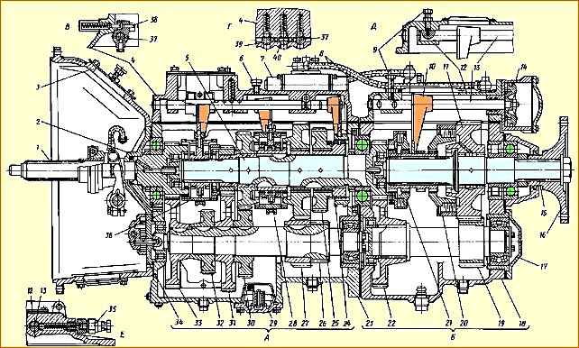
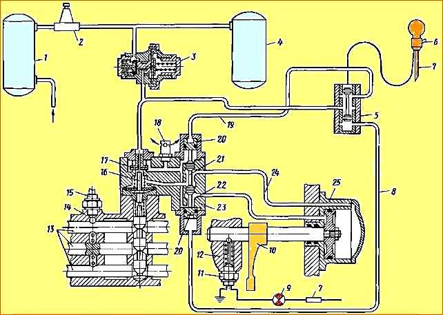
Gearbox: A - main gearbox; B - additional box; B - reverse gear fuse; D - section through the clamps and locks of the rods in the main box; D - locking device for turning off the additional box when towing a car; E - indicator sensor for switching on the additional box; 1 - input shaft; 2 - input shaft cover, 3 - clutch housing; 4 - top cover of the main box; 5 - secondary shaft of the main box; 6 - breather; 7 - air distributor; 8 - air ducts; 9 - locking bolt for turning off the additional box when towing a car; 10 - fork; 11 - secondary shaft gear of the additional box; 12 - top cover of the additional box; 13 - rod; 14 - pneumatic cylinder; 15 - secondary shaft of the additional box; 16 - flange for fastening the universal joint; 17 intermediate shaft bearing cover; 18 additional box housing; 19 - intermediate shaft of the additional box; 20 - large synchronizer; 21 - small synchronizer; 22 - reduction gear; 23 - main box housing; 24 - reverse gear carriage; 25 - reverse gear; 26 - intermediate shaft of the main box; 27 - first gear gear; 28 - synchronizer for engaging 1st and 2nd gears; 29 - oil pump intake; 30 - 2nd gear gear; 31 - 4th gear gear; 32 - power take-off gear; 33 - intermediate shaft drive gear; 34 - oil pump; 35 - switch; 36 - synchronizer for engaging III - IV gears; 37- reverse gear fork rod; 38 - reverse fuse; 39 - shift fork rod for III, IV gears; 40 - rod for shifting 1st and 2nd gears
The gearbox structure is shown in Fig. 1.
Installation of all gearbox parts is carried out in the housings of the main and additional gearboxes, which are interconnected, and then assembled to the clutch housing: a single power unit is formed consisting of the engine, clutch and gearbox.
Input shaft 1 of the main box is mounted on two ball bearings; clutch driven discs are installed at the front splined end, and the rear end is made in the form of a ring gear of a constant mesh gear of the main box.
The secondary shaft 5 of the main box is supported at the front by a cylindrical roller bearing installed in the bore of the gear ring of the drive shaft, and at the rear on a ball bearing mounted in the front wall of the crankcase of the additional box.
The rear end of the secondary shaft is made in the form of a ring gear, which is a constant meshing gear of the additional box.
The gears of the second and fourth gears of the secondary shaft of the main box are mounted on sliding bearings made in the form of steel bushings with a special coating and impregnation, and the first gear and reverse gears are mounted on roller bearings.
The intermediate shaft 26 of the main box is supported at the front by a roller bearing mounted in the front wall of the main box crankcase, and at the rear - on a double-row spherical bearing placed in a cup mounted in the rear wall of the main box crankcase.
An additional axle for the reverse intermediate gear is installed in the crankcase bosses of the main box.
The reverse gear is engaged by moving the reverse carriage 24 forward until it is connected to the ring gear of the reverse gear 25, which is in constant engagement with the reverse intermediate gear.
The secondary shaft 15 of the additional box is supported at the front by a cylindrical roller bearing located in the bore of the gear rim of the secondary shaft of the main box, and at the rear by two bearings: a cylindrical roller bearing and a ball bearing, installed respectively in the rear wall of the crankcase of the additional box and the bearing cover of the secondary shaft.
On the splines in the middle part of the secondary shaft of the additional box, gear shift synchronizers are installed, and on the rear spline end there is a driveshaft mounting flange.
On the middle cylindrical part of the shaft, gear 11 of the additional box is installed on cylindrical roller bearings.
The intermediate shaft 19 of the additional box is supported at the front by a cylindrical roller bearing installed in the front wall of the crankcase of the additional box, and at the rear by a double-row spherical bearing located in a cup mounted in the rear wall of the crankcase of the additional box.
At the front splined end of the intermediate shaft of the additional box, gear 22 of the reduction gear is installed.
At the rear of the intermediate shaft there is a gear ring mated to the reduction gear of the secondary shaft of the additional box.
To engage gears, inertial synchronizers with conical friction rings are used in the main gearbox, and friction discs are used in the additional gearbox.
Gear shifting in the main gearbox is carried out using a mechanical remote drive, and the additional gearbox is controlled using a pneumatic drive.
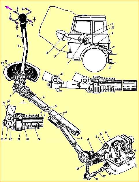
Remote drive of the main box (Fig. 2). Telescopic type, consists of a mechanism located directly on the gearbox 13, and a system of rods and levers connected to the 3 gear lever mounted in the cabin.
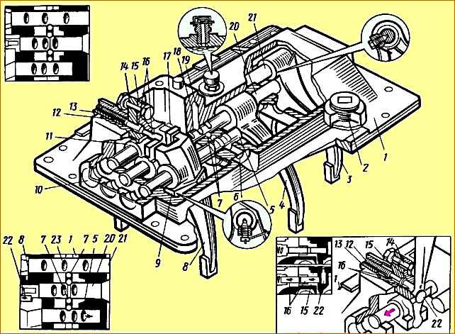
In the lugs of the top cover 1 (Fig. 3) of the main box, three rods are mounted: on the far right (along the direction of the car) there is a fork 3 for shifting the reverse gear, on the middle one there is a fork 4 for shifting the first and second gears of the main box and on the third - fork 8 for switching the third and fourth gears of the main gearbox.
Rods 5, 20 and 21 move in the guide supports of the top cover using lever 22. There are heads (11 and 17, respectively) on the reverse rod and the shift rod for the first and second gears of the main box.
Lever 22 enters head 17 directly, and into head 11 through reverse gear lever 15.
To engage the third and fourth gears of the main gearbox, the lever 22 can fit directly into the groove of the fork 8 for shifting these gears.
The position of the reverse rod is fixed in the cover using a fuse 16, which is included in the driver 15 under the action of a spring 12 placed in a special glass 13.
Only by overcoming the spring force of this fuse can reverse gear be engaged.
The rods, when the gear is engaged and in the neutral position, are held by ball clamps; to prevent the possibility of simultaneous engagement of two gears, a special ball-type lock is installed in the rods.
On the top cover of the main box there is mounted a housing 11 (see Fig. 2) of the remote control mechanism for the main box, in which there is a gear shift shaft 12 with a lever 14 fixedly mounted on it and an intermediate lever 18 connected to the longitudinal rod 7 of the remote drive .
In the housing of the remote mechanism there is a ball retainer 9 for gear selection.
Longitudinal rod 7 can perform both longitudinal and angular movements.
The angular movement of the rod causes an axial movement of the shaft 12, which leads to the connection of the lever 14 sitting on it with a certain slider in the upper cover of the main box 13.
Longitudinal movement of the longitudinal rod causes rotation of the gear shift shaft 12 and the lever 14 sitting on it. In this case, the gear shift fork rod moves together with the fork until the corresponding gear is engaged.
The additional box is controlled using a pneumatic valve by range switch 1 (see Fig. 2), located on the handle of gear shift lever 3.
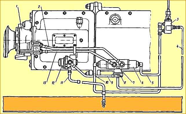
The switching mechanism for the additional box (Fig. 4) - Consists of a pressure reducing valve 12, an air distributor 6, a pneumatic valve 5, an inlet valve 8, a working cylinder 1 and air ducts.
Reducing valve 3 (Fig. 5) serves to reduce the pressure of compressed air supplied from the vehicle’s pneumatic system to 4.75 kgf/cm 2 - the operating pressure of the gearbox pneumatic system.
Air distributor 23 directs compressed air from the intake valve 17 into one or another cavity of the working cylinder 25 and bleeds air from its cavities.
Pneumatic valve 5 controls the air distributor.
When the 6-range switch is lowered down, the air distributor spool is set to the position corresponding to direct transmission in the additional box. With the switch raised to the downshift position.
The inlet valve 17 ensures the supply of compressed air through the air distributor 23 to the working cylinder 25 only when the gear in the main box is turned off.
When the gear is engaged in the main box, the valve inlet is closed by pusher 16 and air does not enter the air distributor and the working cylinder, the relief hole in the valve body is open, both cavities of the working cylinder are connected to the atmosphere.
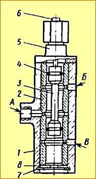
When range switch 1 is raised (see Fig. 2), cable 6 moves spool 3 (Fig. 6) to a position in which compressed air supplied from the pressure reducing valve to channel “A” through the pneumatic valve channel enters channel “ B" and then to the air distributor to engage the downshift.
Channel “B”, at this time through filter 8 is connected to the atmosphere.
When the range switch is lowered, the cable moves spool 3 to a position in which compressed air through channel “A” enters channel “B” and from there to the air distributor to engage direct transmission. At this time, channel “B” is connected to the atmosphere through cover 5.
The gear shift mechanism of the additional gearbox is located in the upper cover of its crankcase.
Rod 13 is located here (see Fig. 1), connected to the piston of the pneumatic cylinder 14.
The direction of movement of the rod with the gear shift fork 10 of the additional box attached to it depends on the pressure supplied to the pneumatic cylinder to the left or right of the piston, which causes the activation of the large 20 or small 21 synchronizer, i.e., the reduction or direct transmission of the additional box.
A downshift indicator sensor is installed on the top cover of the additional box.
When the rod 13 and fork 10 move the gear shift of the additional gearbox from one position to another, the control light connected to the switch terminal 35 lights up in the driver’s cabin.
The light goes out as soon as the selected (direct or reduction) gear is fully engaged.
In addition, there is a locking device on the top cover of the auxiliary box to disable the auxiliary box when towing the vehicle.
To do this, having installed the fork 10 in the neutral position, screw the locking bolt 9 all the way into the hole made on the rod and lock it in this position with a nut.
The gearbox lubrication system is combined: the gear bearings of the secondary shafts of the main and additional boxes are lubricated under pressure, the gear teeth and shaft bearings are lubricated by splashing.
Oil is sucked from the crankcase oil bath through intake 29 and a system of channels by gear oil pump 34.
The pump is driven from the end of the intermediate shaft of the main box.
The pump has a pressure reducing valve, which is adjusted to a pressure of 0.78 kgf/cm 2 and when the oil pressure increases excessively, it connects the pump discharge channel to the suction channel.
The oil baths of both crankcases are connected to each other by a channel to ensure the same oil level in them.
The internal cavity of the gearbox housings communicates with the atmosphere using a breather.
The gearbox has an oil filler hole on the cover of the main box, an oil level control hole on the side wall of the main box crankcase, and two drain holes each at the bottom of the main and auxiliary gearbox crankcases.
")

")
")
")
")
")
")
")