Operating principle of Common Rail Sistem 2
Battery-type fuel system - Commonrailsistem 2 (SEZ2) with electronic fuel supply control manufactured by Robert Bosch (Germany).
CRS2 BOSCH with electronic control unit provides:
- - precise dosage of cyclic fuel supply for each operating mode;
- - adjustment of fuel injection advance angles depending on speed, load, temperature;
- - easy engine starting with minimal emissions of harmful substances into the atmosphere under any temperature conditions;
- - adjustment of the fuel supply process depending on environmental conditions in order to reduce emissions of harmful substances;
- - compatibility with the vehicle’s electronic control unit (ABS, ASR, cruise control, etc.).
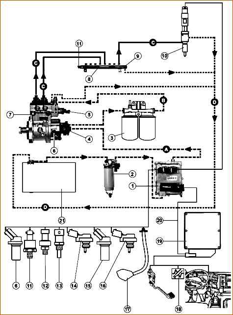
Components of the electronic fuel injection system "Common Rail Sistem 2": 1 - electronic engine control unit with cooler (ECU) (650.3763010); 2 - fuel coarse filter (installed by the consumer); 3 - fine fuel filters (650.1028010 - assembled); 4 - fuel priming; 5 - solenoid metering valve of the fuel pump (650.1111674); 6 - fuel shaft speed sensor (phase sensor); 7 - fuel pump (650.1111005); 8 - ramp (650.1112552); 9 – bypass valve; 10 - nozzles (650.1112010); 11 - rail pressure sensor (650.1130540); 12 - oil pressure sensor (650.1130552); 13 - temperature sensor in the cooling system circuit (650.1130556); 14 - pressure and air temperature sensor in the intake manifold (650.1130548); 15 - engine crankshaft speed sensor (650.1130544); 16 - fuel pressure and temperature sensor; 17 - fan shut-off clutch; 18 - emergency warning light (ChekEngen); 19 - Electronic vehicle control unit; 20 – train. Hydraulic circuits: (A) - suction system; (B) - low pressure system; (C) - high pressure system; (D) - return system to the fuel tank (21).
The fuel system works as follows:
Fuel from the fuel tank through the coarse settling filter and the cooler of the electronic control unit is sucked in by the fuel priming pump and, under a pressure of 700-800 kPa (7-8 kgf/cm 2), is supplied to the fine filter with very high degree of cleaning, since the CommonRail system is more sensitive to contamination than systems with a conventional plunger fuel pump.
The fuel then enters the high-pressure fuel pump, which has two sections, each of which is fed through a metering device with an electric valve.
From the fuel pump, fuel under pressure enters a common fuel accumulator line (ramp) and is then supplied to each injector through individual fuel lines.
Injectors supply fuel under pressure into the combustion chamber, the injection duration is determined by the duration of the electrical pulse from the engine's electronic control unit.
The peak electrical pulse to the injector is characterized by a voltage of up to 80 V and 20 A.
Fuel injection is carried out in stages:
- - pilot injection (1-3%) at early injection advance angles - to reduce engine noise;
- - main injection (94-96%);
- - additional injection after the main one - to reduce exhaust smoke (1-5%).
The balance of injected fuel for the indicated injections is determined by the engine operating mode.
Electro valves allow you to regulate the pressure of fuel entering the space above the plunger of the fuel pump.
In the ramp fittings at the entrance to the high-pressure pipelines there are hydraulic fuel flow limiters (one for each cylinder), which shut off the fuel supply to the injectors when the specified injection duration is exceeded (for example, when the injector is clogged).
After eliminating the injector failure, normal operation of the limiter is restored automatically.
Sensors located on the engine transmit information to the electronic control unit about the operation of the systems.
The electronic control unit uses this information to control injection and send signals about the operation of other systems to the instrument panel, and control the actuators that ensure engine operation.
This information comes from heating sensors (see Fig. 3):
- - rail pressure sensor (1);
- - phase sensor (2);
- - temperature and air pressure sensor in the intake manifold (3);
- - engine speed sensor (4) (on the flywheel housing);
- - oil pressure sensor (5);
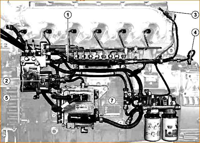
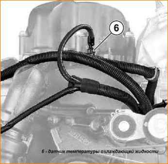
- - coolant temperature sensor (6) (see Fig. 3);
- - fuel temperature and pressure sensor (7);
- - fan operating mode sensor (built into the fan clutch).
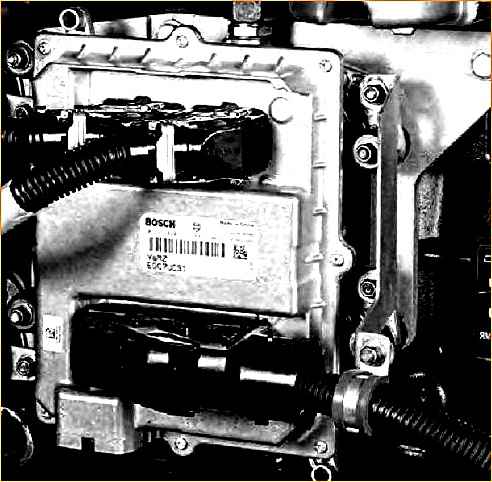
Electronic control unit (ECU)
The electronic control unit (see Fig. 4a) receives information from sensors and the computer unit that controls the car.
Depending on the input parameters, this unit controls fuel injection and a number of auxiliary functions (engine fan).
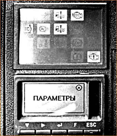
This unit informs the driver about the status of the fuel injection system through indicators (lights, lights) located on the instrument panel (see Fig. 46), and in the event of any malfunction it operates in emergency mode.
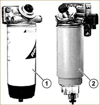
Coarse fuel filter. (see Fig. 5) Full-flow sediment filter with water separator, manual fuel pump and replaceable filter element (installed on the vehicle). (1) - MAZ car filter, (2) - Ural car filter.
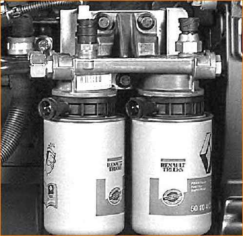
Fine fuel filter. (see Fig. 6) Full-flow filter with two replaceable filter elements and a device for automatic heating of fuel in the cold season.
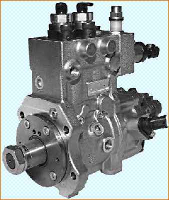
High pressure fuel pump. (see Fig. 7)
With gear fuel priming pump and two high pressure plunger sections, gear driven; drive ratio 0.5:1.
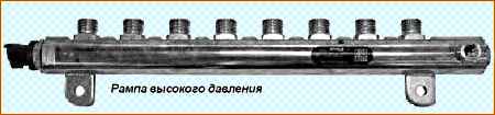
High pressure ramp (see Fig. 8)
It provides communication between the pump and the fuel injectors.
The ramp is equipped with:
- - pressure sensor,
- - bypass valve.
The bypass valve protects the high pressure circuit from overpressure by diverting fuel to the tank return system. Bypass valve calibration: 1650± 50 bar.
The rail pressure sensor at a 5-volt supply voltage produces an output voltage in the range of 0.5 - 4.5 volts, depending on the value of the measured pressure.
Information about this value is transmitted to the engine ECU.
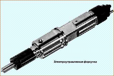
Electrically controlled nozzle (see Fig. 9)
This nozzle includes an electric valve that controls the opening and closing of the atomizer.
The electrically controlled nozzle cannot be repaired. The sealing gaskets must be replaced after each dismantling. The clamps are not polarized.
Fuel supply fitting to the injector. (650.1112154)
Equipped with a device that prevents it from rotating using two balls. This fitting, like its seal, must be changed every time it is dismantled.
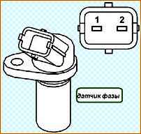
Phase sensor. (See Fig. 10) This inductive type sensor produces a sinusoidal voltage caused by the passage of the flywheel and pump gear cavities.
The frequency of this signal is proportional to the engine rotation speed. There are 58 grooves on the flywheel.
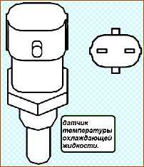
Coolant temperature sensor. (see Fig. 11)
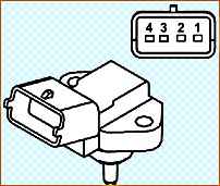
Air pressure and temperature sensor in the intake manifold. (see Fig. 12) One sensor has 2 measuring elements built in.
With a 5-volt supply voltage, this sensor produces an output voltage between 0.5 V and 4.5 V.
- Technical data (between terminals 1 and 2).
Temperature (º C) – Resistance (Q):
0 – 6600 → 5900;
10 – 4200 → 3800;
20 – 2760 → 2500;
30 – 1870 → 1700;
40 – 1280 → 1180;
50 – 900 → 830.
Oil pressure sensor. (see Fig. 13)
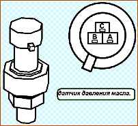
With a 5-volt supply voltage, this sensor produces a certain voltage depending on the pressure in the oil circuit (from 0 to 7 bar).
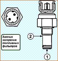
Fuel filter clogging sensor. (see Fig. 14) Switches when the pressure difference between P1 (1) and P2 (2) reaches approximately 3 bar.
Information about filter clogging is transmitted to the display only when the engine is hot (to avoid identifying malfunctions that appear during peak pressure situations or due to an increase in fuel viscosity in the cold season).
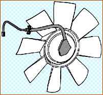
Fan clutch. (see Fig. 15)
The fan clutch consists of a rotation speed sensor and a viscous coupling control valve.
The electronic computer unit controls the viscous coupling via an electrovalve according to the parameter required by the engine (temperature, reduced efficiency mode, turning on the heater or air conditioner).
This system operates at very high injection pressure (up to 1400 bar) with medium voltage current.
Before disassembling, thoroughly clean the system and then take all necessary precautions to prevent any contamination from entering the system.
Use clean solvent and blow with compressed air. During normal operation, after stopping the car, the pressure in the high-pressure circuit drops quickly (1-3 minutes).
It is necessary to ensure that there is no pressure in the circuit by creating a fuel leak by loosening the injector fitting.
All work on the injection system must be carried out with the engine stopped.
Repairs should be carried out in a clean room, protected from dust, using suitable products and tools. The use of gloves made of fibrous material is prohibited.
Clean the parts thoroughly with solvent and check them carefully.
Use the best quality brushes, checking their cleanliness and condition. The use of fibrous and dirty rags is prohibited.
Plug all holes with special plugs and plugs as soon as the pipelines have been dismantled.
Avoid use of compressed air. The injector mounting brackets cannot be repaired.
If they fail, replacement is necessary.
When testing the injectors, proceed with great care to avoid injury from fuel spray or high pressure leaks.
Follow the chronological order of disassembly and assembly operations described in the repair manual.
When re-installing, do not make any modifications or apply excessive force.
If necessary, replace the part. Always tighten to the recommended torque.
Bleed the circuit without using the starter.
By following the above recommendations, the quality and reliability of the “CommonRail” system are ensured.
New tubes have internal surfaces coated with a protective anti-corrosion substance. The tubes should be washed and wiped with industrial alcohol and then immediately replaced in place to avoid corrosion.