The vehicles are equipped with service, parking, spare and auxiliary brake systems, as well as devices for connecting the brake system of a semi-trailer with a two-wire pneumatic drive and outputs for supplying other consumers with compressed air
The service brake system affects the braking mechanisms of all wheels of the vehicle.
Mechanism drive is pneumatic with separate braking of front and rear wheels.
Electro-pneumatic pressure modulators of the anti-lock braking system (ABS) brakes can be installed in the brake drive.
Parking and spare brake systems act on the brake mechanisms of the middle and rear axles,
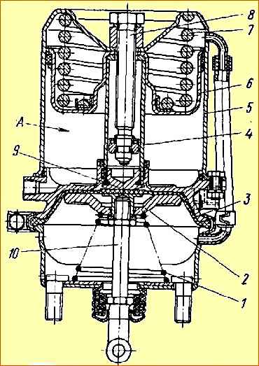
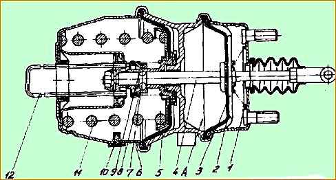
which are activated using brake chambers with spring energy accumulators (Fig. 1, 2). Control is carried out using a crane in the driver's cabin.
The parking brake system also functions as a spare one.
It is designed to brake the vehicle in the event of a complete or partial failure of the service brake system.
When the parking brake system is turned on, the control valve handle is set (by turning) to its extreme fixed position.
Compressed air, compressing the power springs of energy accumulators, is released into the atmosphere, and the spring activates the brake mechanisms.
When the emergency brake system is activated, the parking brake control valve handle is held in any intermediate non-fixed position.
As the angle of rotation of the handle increases, the intensity of braking increases due to a decrease in air pressure compressing the springs of the energy accumulators.
The parking brake system of MAZ-631705, 631708, 642505, 642508, 533605 vehicles can be made in two versions:
1) The parking brake system acts on the brake mechanisms of the middle and rear axles, which are actuated by brake chambers with spring energy accumulators.
Control is carried out using a crane in the driver's cabin.
The same system serves as a spare one. It is designed to brake the vehicle in the event of a complete or partial failure of the service brake system.
When the emergency brake system is turned on, the parking brake control valve handle is held by the driver in any intermediate non-fixed position.
As the angle of rotation of the handle increases, the intensity of braking increases.
2) The parking system consists of two independent systems: the main one, acting through the transmission on the wheels of the middle and rear axles of the vehicle, and an additional one, acting on the wheels of the rear axle and controlling the brakes of the trailer.
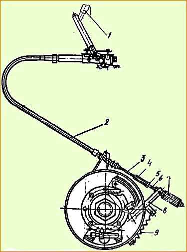
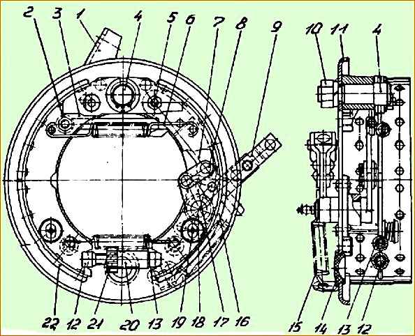
The main parking brake system includes a drum brake (Fig. 3), installed on the output shaft of the transfer case in the drive of the middle and rear axles, and a mechanical, manually controlled multi-pass brake drive (Fig. 4).
The additional parking brake system includes the service brakes of the rear axle of the vehicle, the drive circuit for the trailer brakes and the brakes of the rear axle of the vehicle, and a manually operated valve.
The crane has a follow-up action angle of rotation of the handle, which allows you to adjust the intensity of braking when using this brake system as a spare.
An additional parking brake system is used for short-term braking of a road train together with the main braking system on roads with a slope of more than 12%.
The auxiliary brake system acts on the vehicle's transmission by creating back pressure in the exhaust system using an air-actuated throttle body.
It is designed to slow down the car on long descents of mountain roads. When turning the valve, the fuel supply is simultaneously turned off.
When the tractor vehicle is braked by the working or parking (spare) systems, the semi-trailer is simultaneously braked.
Schemes of the pneumatic drive of the brakes are given in the article - "Schemes of the pneumatic drive of the brakes"
The operation of the mechanisms is described in the article - “How brake mechanisms work”
Possible brake malfunctions
The air cylinders of the pneumatic system do not fill or fill slowly (the pressure regulator does not work):
- The pneumatic system has a significant leak of compressed air. Hoses and pipelines are damaged. insufficient tightening of connections, pipes, hoses, joints and transition fittings - Replace hoses and pipes. Tighten the connections. Replace faulty parts of connections and seals
- Insufficient tightening of device body parts. The body parts of the devices are leaking due to poor-quality casting - Tighten the fastening of the body parts. Replace the device
- The device is faulty. Leakage occurs through the atmospheric outlet of the device - Replace the device
- Air cylinder leaking - Replace cylinder
- The drying cartridge of the air dryer is frozen or clogged - Check the air outlet from terminal 21. If there is a malfunction, warm the cartridge with hot water
- Continuous release of air through the outlet window of the compressed air dryer (in winter) - See description of the dryer
The air cylinders of the pneumatic system are not filled (the pressure regulator is activated):
- The pressure regulator is not adjusted correctly - Adjust the pressure regulator with the adjusting screw, if necessary, replace the pressure regulator
- Presence of kinks and collapse of pipelines - Replace the pipeline
- Presence of a transport plug or foreign bodies in the pipeline - Remove the plug and foreign objects, blow out the pipeline with compressed air
- 4-circuit safety valve not adjusted correctly - Check and adjust or replace if necessary
The pressure in the circuit cylinders is high or low when the pressure regulator is operating:
- The pressure gauge is faulty - Replace
- The pressure regulator is not adjusted - Adjust the regulator using the adjusting screw. If not adjustable, replace the regulator
- 4-circuit valve not adjusted correctly - Adjust or replace
Ineffective braking or lack of braking of the vehicle by the service brake when the brake pedal is fully depressed:
- Brake valve faulty - Replace brake valve
- Contamination of the cavity under the rubber boot of the two-section brake valve drive lever - Clean the dirt from the cavity under the rubber boot. Replace the cover if necessary
- The presence of a significant leak of compressed air in the lines of the first and second circuits after the brake valve - Replace the hoses and pipelines. Tighten the connections.
- The brake valve drive is not adjusted - Adjust the drive
- Incorrect installation of the brake force regulator drive - Adjust the installation of the brake force regulator or replace the brake force regulator
- The stroke of the brake chamber rods exceeds the specified value - Adjust the stroke of the rods, Replace the adjusting lever (with automatic adjustment)
- Brake pad wear - Check the thickness of the brake linings and replace the pads if necessary
When the parking brake valve handle is set to the released position, air leaks from the brake valve or accelerator valve:
- Rupture of the diaphragm of the rings in the trailer brake control valve - Air should not enter terminal 42 of the trailer valve. Replace worn parts and trailer brake control valve
- The seal between the cavity of the energy accumulator and the working chamber is broken - Identify the damaged chamber and replace
Ineffective braking or lack of braking of the vehicle with parking or emergency brakes:
- Faulty accelerator valve, parking brake valve - Replace the brake apparatus
- Pipelines or hoses on the supply circuit of a manual faucet are clogged - Clean the pipelines and blow them out with compressed air. If necessary, replace with working ones
- Spring energy accumulators are faulty - Replace brake chambers with spring energy accumulators
- The strokes of the brake chamber rods exceed the set value - Adjust the stroke of the rods
When the parking brake valve handle is set to the released position, the car does not release the brakes:
- Air leakage from the piping of the supply circuit of a manual valve from the atmospheric outlet of the relay valve - Eliminate the location of the leak using the methods indicated in paragraph 1
- The thrust bearing of the spring energy accumulator has failed - Replace the brake chamber with the spring energy accumulator
- Parking brake valve is faulty - Determine whether air is entering terminal 4 of the parking brake accelerator valve. Replace the faucet
- Relay valve defective - Replace valve
- Air leak from spring accumulator - Replace spring accumulator brake chamber
When the vehicle is moving, the rear trolley brakes without actuating the brake pedal and the parking brake valve:
- The brake valve is faulty. The brake valve actuator is not adjusted correctly - See adjusting the brake valve actuator
- The seal between the cavity of the spring energy accumulator and the working chamber is broken - Replace the brake chamber with the spring energy accumulator
- Insufficient pressure in the parking brake circuit - Check the pressure in the circuit. Check 4-circuit valve
Ineffective braking of a trailer (semi-trailer) or lack of braking when the brake pedal is pressed or the emergency brake is on:
- Compressed air leak - Eliminate using the methods indicated in point 1
- The two-wire trailer brake control valve drive devices and connecting heads are faulty - Replace the faulty parts
- Trailer brakes or trailer brakes are faulty - Check the presence and level of pressure in the coupling heads of the tractor. Check the condition of the trailer brakes
There is no braking of the road train when the auxiliary brake is turned on:
- The pneumatic valve for activating the auxiliary brake is faulty. - Replace the tap
- The pneumatic cylinder of the auxiliary brake flap drive is faulty. The fuel shut-off cylinder of the damper mechanism is faulty. Compressed air leak
- Pipelines are clogged - Replace faulty cylinders. If necessary, remove the auxiliary brake components, clean off carbon deposits, wash and dry
- Fix the leak using the methods specified in point 1. Remove the pipelines and blow them with compressed air
- The brake lights do not come on when you press the brake pedal or apply the parking brake
- The brake light sensor or pneumatic drive devices are faulty - Replace the sensor or devices
Presence of a significant amount of oil in the pneumatic system:
- Cylinder piston rings worn - Replace compressor
")

")
")
")
")
")
")
")