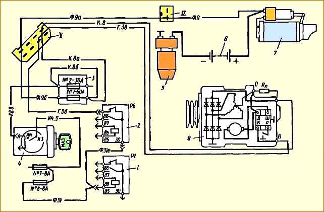
The electrical power system of automobiles consists of two sources: batteries and an alternating current generator set.
In addition, the system includes a number of intermediate relays, a battery mass switch and a key switch for instruments and starter
The connection diagram for power supply system products is shown in Fig. 1.
The G273A generator set (GS) is an alternating current generator with a built-in rectifier unit and an integrated voltage regulator (IVR).
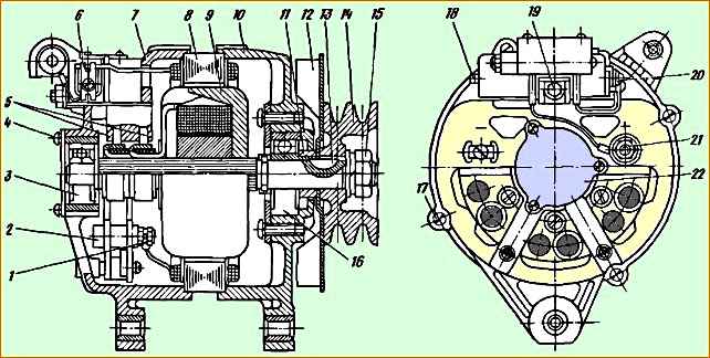
Generating set: 1 - nuts securing the phase terminals of the stator winding: 2 - rectifier unit; 3.16 - bearings; 4 - screw securing the protective cover; 5 - brushes; 6 - brush holder with IPH, make-up resistance and brushes; 7.10 covers; 8 - stator; 9 - rotor; 11 - spacer sleeve, 12 - fan; 13 - key; 14 - pulley; 15 - nut; 17 - tension screw; 18 - screw for seasonal voltage regulation; 19 - terminal “B” of the brush holder; 20 - screw for connecting the neutral wire of the stator winding; 21 - terminal “+”; 22 - protective cover
Technical characteristics of the generator set
- Rated power, W - 800
- Rated voltage, V - 28
- Rectified current, not less, A - 28
Rated rotor speed at ambient temperature and power supply 25 ± 10˚С and voltage 27-28 V, min -1:
- - at a load current of 10 A, no more than - 1550
- - at a load current of 20 A, no more - 2100
Maximum rotor speed, min -1 - 8000
Excitation current, A - 3.3
IVR setting voltage at load current 20 A, rotor speed of PG 3500 ± 200 min -1, ambient temperature 25 ± 5 °C and battery on, V:
- - in the position of the seasonal adjustment regulator “winter” - 28, - 30.2
- - in the “Summer” position of the regulator - 27.0 —- 28.0
pressure of brush springs on the brushes when compressing the springs to 17.5 mm, kgf - 0.3
Weight of PG without pulley no more, kg – 5.4
The generator (Fig. 2) is a three-phase synchronous electrical machine with electromagnetic excitation and is one of the power sources for electrical equipment.
Equipped with a rectifier unit and an integral voltage regulator.
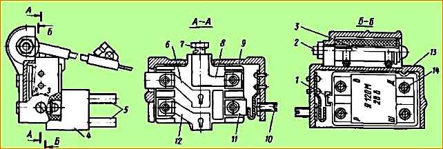
Brush holder with IRN: 1.13 fixing protrusions that protect the regulator from incorrect installation; 2 - screw for fastening the make-up resistance: 3 - make-up resistance R = 75 Ohm; 4 - brush holder; 5 - brushes; 6 - current-carrying busbar from the brush to terminal “D” of the IRN; 7 - screw of the current-carrying terminal “B” of the brush holder; 8 - current supply bus from terminal “B” of the brush holder to terminal “B” of the IRN; 9 - brush holder casing; 10 - screw for seasonal voltage regulation; 11 - current supply bus of terminal “P” of the brush holder; 12 - current supply bus of terminal “Ш” of the brush holder; 14 - integrated voltage regulator; seasonal adjustment screw position: “L” when working in summer; “3” when working in winter
The small-sized integrated voltage regulator Y120M is used to maintain the voltage generated by the generator within specified limits.
The regulator is an electronic device, closed with a lid and filled with a special sealant. The regulator has 4 pins.
With these leads, the regulator is installed in the brush holder so that the leads marked with the letters “W”, “D”, “B”, and “P” lie on the current-carrying busbars of the brush holder (Fig. 3).
The brush holder also contains a 75 Ohm feed resistance 3, which serves to ensure reliable excitation of the generator set at low engine speeds.
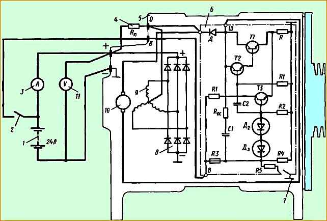
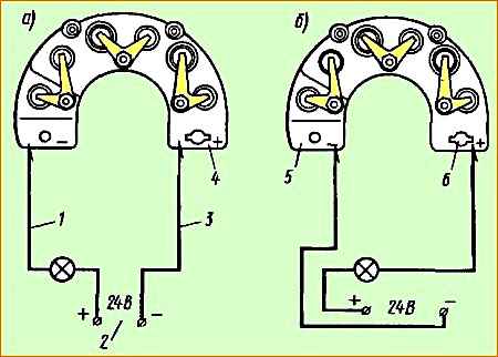
Check diagram for the generator set: 1 - battery: 2 - switch; 3 - ammeter 30 A; 4 - make-up resistance laziness; 5 - generator set; 6 - integrated voltage regulator; 7 - seasonal voltage regulation regulator; 8 - rectifier block; 9 - stator winding; 10 - excitation winding; 11 - voltmeter 30 V
The electrical diagram for connecting the generator with the voltage regulator is shown in Fig. 4.
Generator maintenance
After 50,000 km of vehicle mileage and subsequently at each maintenance-2, it is necessary to remove the power steering unit from the engine, disassemble it, and check the condition of the ball bearings and electric brushes. Damaged bearings and brushes worn down to 8 mm should be replaced.
During the operation of vehicles, the following rules must also be observed:
- - do not allow incorrect connection of wires to batteries or installation of batteries with reverse polarity. This will lead to immediate failure of the rectifier diodes of the GU and IRI;
- - do not disconnect the wires from the positive terminal of the power unit and from the batteries when the engine is running. This will sharply reduce the load on the generator, which can lead to failure of the pump;
- - do not check the serviceability of the GU by shorting the terminals “+”, “B”, “O” to ground or to each other. This may lead to failure of the IVR or the rectifier unit of the GU;
- - do not connect terminal “Ш” of the brush holder. access to which is open through a window in its casing, with terminals “+” of the generator and “B” of the brush holder. This will lead to failure of the IRN;
- - do not check the serviceability of the electrical circuit with a megger or a lamp with a voltage above 26 V when the power supply is turned on. This can lead to failure of the IVR and the rectifier unit;
- - when carrying out welding work on a vehicle, first disconnect the batteries using the ground switch, remove the wires from the “+” terminals of the GU and “B” of the brush holder, and when carrying out welding work on a road train, additionally remove the plugs from the brushes of the semi-trailer to avoid burning out the connecting electrical cable.
After completing the welding work, make sure that the wire tip on the “+” terminal of the unit is securely clamped with a nut. Loosening the nut in this contact (sparking) will lead to failure of the IVR;
- - when washing the engine, avoid direct contact of water into the PG.
Possible malfunctions of the generator set and ways to eliminate them
- - cause of malfunction
Remedy
No charging current: the voltage indicator arrow is in the red zone of the scale
- - No power to terminals “+” or “B” of the generator set
Check the power circuit and excitation circuit according to the diagram and eliminate the malfunction
No charging current: the voltage indicator arrow is in the red zone of the scale
There is voltage at terminals “+” and “B” when the engine is not running
IRN is faulty
Replace IRN
- - The contact rings of the generator rotor are dirty or oily
Wipe the slip rings with a cloth soaked in gasoline
- - Brushes stuck
Remove the brush holder, remove the brushes, remove dust
Charging current is present: the voltage indicator arrow is in the green zone of the scale
When a large load is turned on (headlights or spotlights), as well as when the engine speed increases, the charging current decreases.
The arrow enters the red zone.
- - Belt tension is loose
Tighten the belts
- - The rectifier unit is faulty
Replace the rectifier unit
- - IRN is faulty
Replace IRN
- - Break in the generator stator windings
Replace IRN or stator
Generator repair
For repairs, the generator set is removed from the engine, for which it is necessary (Fig. 5):
- - turn off the battery mass switch;
- - disconnect the wires from terminals <+" and "B" of the control unit (see Fig. 2);
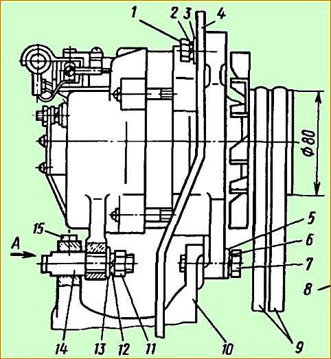
Installation of the generator on the engine: 1, 7.15 bolts; 2, 6, 8,12 - spring washers; 3, 5,13 - flat washers; 4 alternator belt tension bar; 9 - drive belts; 11 – nut
- - loosen bolt 1 (see Fig. 5) of the belt tension bar;
- - loosen nut 11 securing the control unit;
- - loosen bolt 15 securing the pin;
- - unscrew bolt 1;
- - holding the control unit so as not to break the mounting brackets, unscrew bolt 17;
- - remove finger 14; remove the belts from the pulley; remove the control unit from the engine.
The power unit removed from the engine must be cleaned of dust and disassembled in the following order (see Fig. 2):
- - disconnect screw 20 securing the wires;
- - unscrew the two screws securing the brush holder and remove it;
- - unscrew the two screws securing the IRN and remove the regulator;
- - unscrew the three screws 4 securing the bearing protective cover;
- - unscrew the four tightening screws 17 and remove the generator cover 7 along with the stator;
- - unscrew the nuts 1 of the phase leads from the rectifier block and separate the stator 8 from the cover 7;
- - unscrew the nuts securing the “+” terminal on cover 7 and the three screws securing the rectifier block and remove the block;
- - unscrew the nut 15 securing the pulley and remove pulley 14;
- - remove fan 12:
- - knock out key 13 and remove spacer sleeve 11;
- - using a puller, remove cover 10 from the rotor shaft along with the bearing;
- - remove the bearings from covers 7 and 10.
After disassembling, the parts and components of the power unit must be inspected, make sure there is no damage, and also check the serviceability of the windings, rectifier unit and voltage regulator.
The height of the brushes must be at least 8 mm. Worn brushes need to be replaced.
A chipped pulley must also be replaced. The wear of the pulley grooves is checked with a caliper using two rollers with a diameter of 9 mm inserted into the grooves.
The size of the rollers must be at least 83.5 mm. If the size is smaller, the pulley must be replaced. Breakages or cracks in the covers are also unacceptable - such covers must be replaced.
The bearings are carefully inspected. If external inspection does not indicate any abnormalities in the bearings, they can be used for further operation.
When inspecting cover 7, you should pay attention to the drilling of the hole for the bearing. A groove (ovality) is formed in the upper part of the hole. It is necessary to measure the amount of this output.
The size of the hole for the bearing is Ø 35 mm. It is allowed to increase the size up to 35.40 mm. If the size is larger than acceptable, the cover must be replaced.
The holes for the bearing in the cover on the drive side are Ø 47+0.02 mm. Wear up to size Ø 47.04 is allowed.
The holes in the cover brackets must be within the size range Ø 10.2+0.24. If worn out, new bushings are pressed in and the hole is drilled to the specified value.
When inspecting the generator rotor, you should make sure that the bearings are securely fastened to the rotor shaft.
The shaft journals are Ø 15 mm for the bearing in the cover on the slip ring side and Ø 17 ± 0.06 mm for the bearing in the cover on the drive side.
The permitted shaft journal sizes are Ø 14.94 and 16.9 mm, respectively. If the journals are smaller, the rotor must be replaced.
The rotor is checked for a turn short circuit and a short circuit of the field winding to the housing.
The rotor winding resistance should be 3.7 ± 0.2 Ohm at a temperature of +25 °C. A decrease in resistance indicates the presence of a turn short circuit, and the rotor must be replaced.
There may be desoldering of wires from slip rings. In this case, the wires must be soldered to the rings and the soldering area must be painted over.
If the rotor rings have wear, they must be ground and then polished.
The diameter of the rings must be at least 30.0 mm; if the size is less than 30 mm, the rings must be replaced.
The generator stator is checked for a short circuit of the winding to the housing. The check is carried out in the same way as checking the rotor with a test lamp.
The stator winding may have a turn short circuit. This leads to overheating of the stator coils and their failure.
The defect is determined by external inspection by a change in the color of the coils and a violation of their reliable, play-free fit in the stator grooves.
A stator with damaged coils must be replaced.
Check diagram for the rectifier unit: 1 - test lamp; 2 - power supply; 3 - wire with tip; 4 - positive output of the rectifier unit; 5 - negative terminal of the rectifier unit; 6 - shaped hole
The serviceability of the rectifier unit is checked with a test lamp with a voltage not exceeding 24 V, as shown in Fig. 6.
The block is checked in the forward and reverse directions.
To check in the forward direction, the “+” of the constant voltage source is connected through a test lamp to the “—” of the rectifier block, and the “—” of the source is connected to the “+” block (“+” of the block is determined by the shaped hole 6). In this case, the control lamp should be on (see Fig. 6, a).
If the polarity is reversed (see Fig. 6, b), the lamp should not light. If these conditions are not met, the unit is faulty and must be replaced.
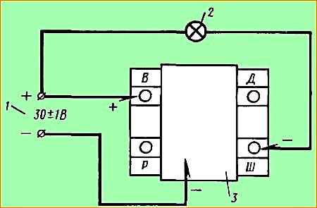
Voltage regulator test diagram: 1 - power supply terminals; 2 - control lamp; 3 - voltage regulator
Integral regulator The voltage level is checked using a test lamp connected to a DC voltage source of 24 - 26 V (Fig. 7).
To check, connect the “+” of the power supply to the “B” terminal of the regulator, and “-” to the base. The control lamp turns on at the “+” of the power source and terminal “Ш” of the regulator.
If the regulator is working properly, the control lamp lights up at full voltage evenly. If the lamp does not light or does not burn at full intensity, or blinks, the IRN is faulty and must be replaced.
After checking the parts and units of the PG, sorting and replacing parts, assembly is carried out in the reverse order.
The assembled PG is checked by turning it by hand by the pulley. The rotor should rotate easily, without jamming or knocking, which indicates correct assembly.
Next, the generator must be checked for operability, for which the installation is placed on a stand.
Model 532M, KI-968 or any other stands are used that allow you to change the rotor speed from 0 to 5000 min-1, as well as measure operating current up to 30 A with an accuracy of at least 2 A and voltage up to 30 V with an accuracy of 0.1 V.
The procedure for connecting the GI to the stand is determined by the instructions for the stand.
The circuit shown in Fig. is assembled. 4. Switch 2 is connected to the power unit and the rotor begins to rotate, bringing its rotation speed to 4000 ± 500 min -1.
A working PG should deliver operating current, which is indicated by the ammeter. The amount of current depends on the state of charge of the batteries 1.
The voltage measured by voltmeter 11 with the seasonal adjustment knob in position “L” (summer) should be 27 - 28 V. It is recommended to keep the power unit at rpm in this mode for 3 - 4 minutes, which is a post-repair run-in.
The PG tested in this way can be installed on the engine. Installation is carried out in the reverse order of dismantling.
")

")
")
")
")
")
")
")