The electric torch heating device (ETH) serves to facilitate engine starting at ambient temperatures below -5˚С to -25˚С.
22°С. The device is connected to the engine fuel system and runs on the same fuel as the engine.
Its operation is based on the evaporation of fuel in pin glow plugs and the ignition of these vapors with air.
The resulting torch heats the air entering the engine cylinders.

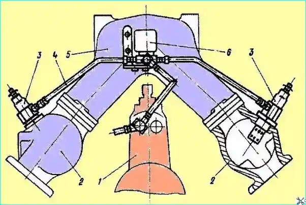
Fig. Diagram of installation of an electric torch device on an engine: 1 - high-pressure fuel pump; 2 - intake manifold; 3 - electric torch plug; 4 - fuel lines; 5 - intake manifold adapter; 6 - electromagnetic fuel valve
The electric torch device includes two electric torch spark plugs 3 (Fig. 1) installed in the threaded holes of the intake manifolds 2 of the engine, an electromagnetic fuel valve 6, a thermal relay with additional resistance; a push-button switch, an electromagnetic relay and a control lamp installed in the vehicle cabin.
The electric torch device is not installed on some engine configurations.
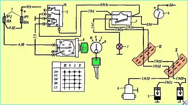
The wiring diagram for the electric torch device is shown in Fig. 2.

Fig. Electric torch device (ETD) diagram: 1 - fuse; 2 - relay P5 for EDT activation; 3 - EDT thermistor; 4 - EDT activation button; 5 - spark plugs; 6 - fuel solenoid valve; 7 - control lamp; 8 - Switch-key: XI, X plug connectors
The electric torch device includes the switch button 4, glow plugs 5, fuel solenoid valve 6, control lamp 7, switch-key 8.
Button 4 is a push-button switch.
When button 4 is turned on, glow plugs 5 are turned on. The working current is supplied to the plugs from button 4 through a thermistor, which contains a thermo-bimetallic element with contacts.
After 60 - 110 seconds after the plugs have heated up, the contacts close and voltage is supplied to the electro-pneumatic valve 6, which opens access for fuel to the EFU injectors.
At the same time, voltage is supplied to the control lamp 7, signaling that the system is ready to start engine.
The starter is turned on, and the fuel-air mixture ignited by the spark plugs enters the engine cylinders, heating them up.
When the starter is turned on, the voltage from the key switch 8 is also supplied to the plug 85 of the RB relay, which closes the contacts of plugs 30 and 87 and supplies voltage to the glow plugs, bypassing the thermistor 3.
This is necessary to maintain the glow of the plugs, since when the starter is turned on, the voltage at the battery terminals drops sharply.
After starting the engine, for more stable engine operation, the driver can maintain the flame torch in the EFU for up to 1 minute by holding button 4 on. Keeping the button on for more than 1 minute after starting the engine is unacceptable.
Maintenance and repair
In the EFU system, glow plugs may fail, which is determined by the control lamp, which will not light.
If one spark plug fails, both spark plugs must be replaced simultaneously.
If thermistor 3 fails, the latter must be replaced, as it cannot be repaired.

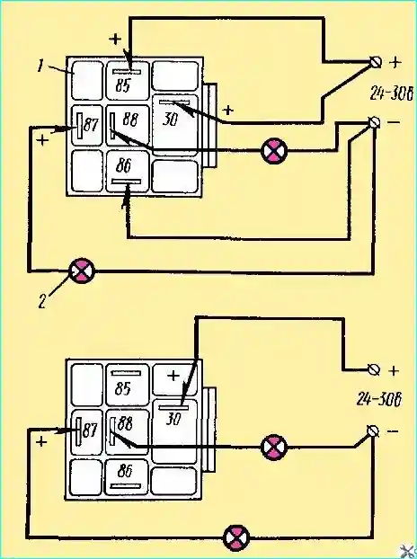
Fig. Relay Check: 1 - relay; 2 - indicator lamp
If relay 2 (P5) fails, reduced voltage will be supplied to the spark plugs during engine starting through thermistor 3, which will result in non-ignition of the mixture and failure of the EFU. In this case, it is necessary to check relay P5.
The relay is removed from the vehicle and checked according to the diagram shown in Fig. 3. The power source voltage should be 24 - 30 V. It is applied to the plug terminals 85 and 86 of the relay.
The voltage on plugs 87 and 88 is checked with a test lamp. If the relay is in good condition, the lamp connected to plug 87 should light, and the lamp on plug 88 should not.
If the voltage is removed from plugs 85 and 86, the lamp connected to plug 87 should not light, and the lamp on plug 88 should light. The faulty relay must be replaced.
Maintenance of the EFU should be carried out when preparing the engine for winter operation, in connection with the transfer of the engine from summer to winter fuel grades, as well as with the need to check the technical parameters of the main components of the EFU: the torch pin plug and the electromagnetic valve.
- 1. Remove the EFU from the engine.
- 2. Parameters for checking the torch pin plug:
- - At nominal rated voltage of 19 V, the current one minute after switching on should be 11.0 -11.8 A.
- - The spark plug jet capacity should be 440 cm³/min at a supplied air pressure of 145 kPa (1.5 kgf/cm²) and a temperature of 20˚± 5˚С.
- 3. Parameters for checking the electromagnetic valve:
- - At a nominal voltage of 24 V, the power consumption is no more than 48 W;
- - The operating (opening) voltage of the valve is 9-15 V;
- - The releasing (closing) voltage of the valve is no more than 6 V;
- - The current consumed by the electromagnetic winding, at an operating voltage of 12 V and an ambient air temperature of 20˚C, should be 0.8-1.1 A;
- - The valve capacity is at least 3.5 l/hour. The valve must be sealed at an air pressure of 150 kPa (1.5 kgf/cm²).
- 4. Blow out the fuel pipes in the system with compressed air under a pressure of 97 kPa (1 kgf/cm²). Air must pass freely in both directions.
In addition, check the tubes for leaks using air under a pressure of 485 kPa (5 kgf/cm²). The inside of the tubes must be clean.
- 5. If the products meet the specifications during inspection, they must be reinstalled on the engine. If there are any deviations in the electrical resistance of the spark plug, replace it.

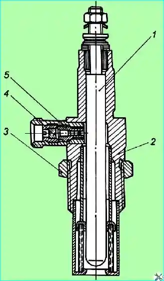
Fig. Torch pin spark plug: 1 - glow pin; 2 - spark plug body assembly; 3 - lock nut; 4 - filter; 5 - metering insert
If the spark plug capacity decreases, unscrew the filter 4 (Fig. 4), remove the metering insert 5, wash them in unleaded gasoline or ethyl alcohol and blow with compressed air. Then install and re-check the spark plug capacity.
- 6. Install the EFU products on the engine. When installing, connect the fuel line from the high-pressure fuel pump to the electromagnetic valve taking into account the direction of the arrow stamped on the valve body.
When installing, lock the pin flare spark plug with a lock nut.
Carefully secure the electromagnetic valve and tighten the fuel line connections securely.
Check and, if necessary, tighten all EFU power supply connections, check the reliability of the plug connections.
- 7. After installing the EFU on the vehicle, bleed the EFU fuel system and check its tightness by pressing the EFU power button with the engine running and holding it for 30 seconds after the indicator light comes on.
Fuel leaks in the system connections are not allowed.
- 8. Check the serviceability of the EFU electrical circuit.
Checking the serviceability of the electrical circuit includes checking the preliminary heating of the spark plugs, heating the spark plug through resistance when the engine is running with the EFU.
Preliminary heating of the spark plugs is assessed by the current consumed by the spark plugs and by the voltage supplied to the spark plugs. The current consumed by the spark plug is about 23 A, the voltage is about 19 V.
Make sure that the generator set automatically switches off during the operation of the EFU.
If the current consumed by the spark plug and the voltage supplied to the spark plug have the same values as during the preheating period, then the automatic shutdown of the generator set is working properly.
If it becomes necessary to replace one spark plug, replace both at the same time
Starting the engine using an electric torch device (ETD)
- 1. Prepare the engine for starting as described above. Set the governor stop lever to position B with the fuel supply on, and turn the governor control lever 3 to the middle position.
- 2. Press the EFD on button and hold it down for the entire time the device is operating. During the glow plug heating period, the ammeter in the driver's cabin should show a discharge current of about 23 A.
- 3. After the indicator light comes on (approximately 60-110 seconds after pressing the EFU switch), turn on the starter.
- 4. After starting the engine, the electric torch device may be operated until a stable rotation speed is reached, but for no more than 1 minute.
If the engine does not start, restart it in the same sequence. It is recommended to start the next glow plug heating 20-25 seconds after the end of the previous engine start.
After installing the EFU on the engine or after a long break in operation, bleed the fuel system by pressing the EFU switch button with the engine running and holding it for about 30 seconds after the indicator light comes on.
Failed glow plugs cannot be repaired.


