To perform repairs, remove the starter from the engine by unscrewing the clamp bolts
Disassemble the starter in the following order:
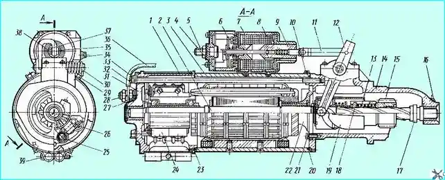
- - remove the protective tape 1 (see Fig. 1);

Fig. Starter: 1 - protective tape; 2 - anchor; 3 - housing; 4 - relay cover; 5 - contact bolt; 6 - contact disk; 7 - starter relay; 8 - starter relay winding; 9 - relay armature; 10, 16, 27 - threaded plugs of lubrication channels; 11 - relay armature rods; 12 - drum drive lever; 13 - spring; 14 - drive-side cover; 15 - gear; 17 - thrust ring; 18 - drive nut; 19 - cup; 20, 23 - sealing rings; 21 - bearing holder fastening bolt; 22 - bearing holder; 24 - electric brushes; 25 - brush holder spring; 26 - electric brush fastening screw; 28 - brush holders terminal bolt; 29 - starter traction relay fastening bolts; 30 - lever spring; 31 - collector-side cover; 32 - lock washer; 33 - tie bolt; 34 - screw for connecting the relay power wire; 35 - pin; 36 - connection busbar; 37 - flat washer; 38 - cotter pin; 39 - screw of the tightening protective tape
- - unscrew the screws 26 of the brush ropes and, having lifted the brush springs 25, remove the brushes from the brush holders;
- - unpin the connection of the lever 12 with the rods 11 of the anchor of the traction relay and remove the finger 35;
- - unscrew and remove the two tie rods 33;
- - remove the cover 14;
- - remove the housing together with the traction relay;
- - unscrew the four bolts of the holder 22 of the intermediate bearing;
- - remove the anchor 2 from the cover 14 together with the drive;
- - remove the two crackers installed in the splines under the thrust ring 17;
- - remove the drive assembly from the anchor shaft.
The starter parts and assemblies must be carefully inspected for faults and breakdowns.
The covers on the drive and collector sides must not have cracks or damage;
- - the gear teeth and electric brushes must not have chips; the drive pin installed in lever 12 must be securely fastened in the lever and not have wear;
- - the electric brush springs must not have breakages. Worn and damaged parts are subject to replacement.
Electric brushes with a height of less than 14 mm must also be replaced (the height of the brushes is measured from the point of contact of the spring to the ground working surface).
Contact bolts 5 and contact disk 6 of the traction relay must not have any burnt spots on the working surface.
If burnt, the contacts are restored using the methods given in the description of starter maintenance.
The traction relay is checked for the integrity of the pull-in and holding windings and for turn-to-turn short circuits.
The check is performed with ampere-voltmeters Ц437, Ц20 or any other, allowing to measure resistance with an accuracy of 0.1 Ohm.
The resistance of the pull-in winding is measured. It should be 0.9 ± 0.2 Ohm. The resistance of the holding winding should be 5 ± 0.8 Ohm.
Remember that the resistance values are given for cold (unheated) coils (ambient temperature 20 ± 5˚C).
If the resistance of the coils differs from the values given above, then there are turn-to-turn short circuits in the coils and the relay must be replaced.
At the starter anchor, it is necessary to inspect the collector, check the winding for turn-to-turn short circuits and the housing. Particular attention should be paid to the condition of the two oval dimples located on the shaft splines.
The dimples should not have wear in the form of rectangular protrusions. Such wear leads to jamming of the drive mechanism during start-up, and the anchor must be replaced.
The surface of the anchor collector is wiped or cleaned as shown in the description of maintenance.
If it is necessary to groove the collector, it is then sanded with fine sandpaper. The size of the commutator after grinding should be at least 56.05 mm.
The anchor is checked using the PPYA-5, PPYA-533 devices, on the Emet-54, Elektrotester or other stands that have a prism and a transformer device for checking anchors.
After wiping and cleaning from dust and accumulated dirt, the starter stator is checked for a short circuit of the windings to the housing.
First, unscrew the two bolts inside the stator that secure the buses to the housing.
The check is performed with a 110 or 127 V test lamp included in the set of devices or stands.
Faulty coils must be removed, the damaged area must be insulated and reinstalled in the housing.
After securing the pole pieces with the coils, the starter housing must be caulked to prevent the coil mounting screws from self-unscrewing.
It is also necessary to check the support bushings of the starter armature shaft installed in covers 14 and 31 (see pfig. 1).
The bushing in cover 14 on the drive side may be worn to a size no greater than 19.615 mm. The size of the bushing in cover 31 on the collector side should not be greater than 18.105 mm.
If the dimensions of the bushings are greater than those specified, the bushings must be replaced. The inner diameter of the bushings after pressing in and boring should be:
- - in the cover on the drive side 19.5+0.045 mm;
- - in the cover on the collector side 18.0+0.035 mm.

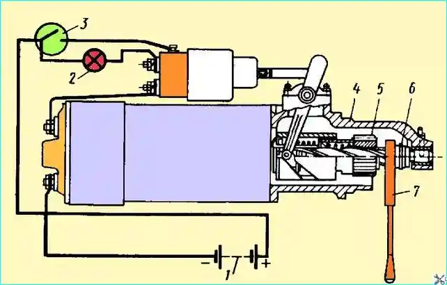
Fig. Starter adjustment: 1 - batteries; 2 - indicator lamp; 3 - starter button; 4 - cover on the drive side; 5 - gear; 6 - thrust ring; 7 - gasket
After replacing parts and repairing, the starter is assembled in the reverse order of disassembly. In this case, bolts 21 (see Fig. 1) for fastening the intermediate bearing holder 22 must be installed on BF-4 glue.
10 drops of turbine or motor oil must be poured into the lubrication holes located under the threaded plugs 10, 16 and 27.
The splines of the anchor shaft are lubricated with TSILTIM-203 grease before assembly. In the assembled and lubricated starter, the anchor should easily turn by hand when force is applied to gear 15.
The assembled starter must be adjusted; to do this, the starter must be clamped in a vice or a device that ensures its immobility.
The circuit shown in Fig. 2. Connect a 24 V test lamp and install a 16 mm thick adjusting shim between the pinion and the thrust ring.
Turn on switch 3. After the starter traction relay is triggered, the lamp should not light.
When installing a 11.7 mm thick shim, the lamp should light when the relay is triggered.
If these conditions are not met, adjust the traction relay: when the lamp lights up and the 16 mm shim, screw the screw into the relay anchor 9 (see Fig. 1); if the lamp does not light up with the 11.7 mm shim, unscrew the screw from the anchor.
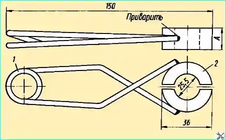
The design of the adjusting shims is shown in Fig. 3.

Fig. Adjusting shims: 1 - retaining spring; 2 - adjusting shims; A=16 or 11.7 mm
The adjusted starter is checked for no-load current from 24 V batteries or from a DC source of the same voltage.
The operating current of the starter should not exceed 110 A. If the current is significantly higher, then the starter anchor rotates tightly and finishing work is required.
The checked and adjusted starter can be installed on the engine. It is important to remember that the fastening of the starter installed on the engine may become loose after several starting attempts.
Therefore, after installing the starter on the engine, it is recommended to make 3-5 test short starts and finally tighten the bolts of the starter mounting clamps. The tightening torque should be 3 kgf.


