Removing the liquid-oil heat exchanger (see Fig. 1)
- 1. Remove the oil supply pipe to the turbocharger (1) (650.1118220).
- 2. Remove the oil drain pipe from the turbocharger (2) (650.1118340).
- 3. Remove heat shield (3) (650.1012510).
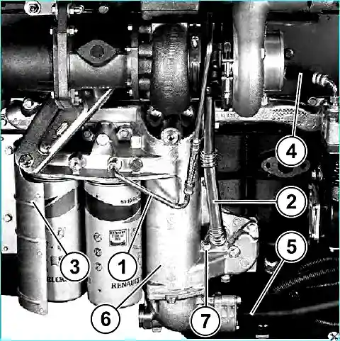
- 4. Remove the coolant supply pipe to the air compressor (4) (650.3509228).
- 5. Remove the pipe leading to the liquid-oil heat exchanger (5) (650.1303150).
- 6. Remove the liquid-oil heat exchanger (6) (650.1013600) complete with oil filter elements (650.1012075).
Disassembly of the liquid-oil heat exchanger (see Fig. 2)
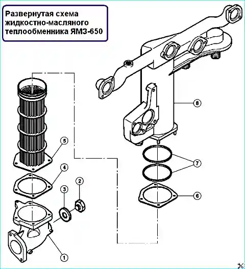
- 1. Remove the tube (1).
- 2. Set aside the spacer (4).
- 3. Unscrew the plug (2).
- 4. Set aside the spacer (3).
- 5. Remove heat exchanger element (5).
- 6. Set aside the spacer (6).
- 7. Remove O-rings (7).
Cleaning the liquid-oil heat exchanger
Oil circuit: use a degreaser. Water circuit: use 5 - 6% aqueous hydrochloric acid solution.
Rinse for 30 minutes. Rinse in 2 - 3% aqueous sodium bicarbonate solution.
Rinse vigorously with water. Dry the parts.
Assembly of the liquid-oil heat exchanger (see Fig. 2)
- 1. Replace the O-rings (7).
- 2. Install seal (6).
- 3. Install the heat exchanger element (5).
- 4. Replace the gasket (3).
- 5. Install plug (2) and tighten to Mcr = 40 ± 5 Nm.
- 6. Replace the seal (4).
- 7. Install the nozzle (1) and tighten to the recommended torque.
Cover of the coolant supply pipe to the heat exchanger 40 ± 5 Nm
Coolant drain plug on heat exchanger tube 40 ± 5 Nm
Oil drain plug on heat exchanger 20 ± 4 Nm
Control of the liquid-oil heat exchanger. (See Fig. 3)
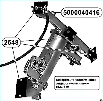
Install tool 2548 + 5000040416. Check the tightness when immersed in hot water (80˚ C) with an air pressure of 6 bar and check for air bubbles
Attachments for controlling the heat exchanger
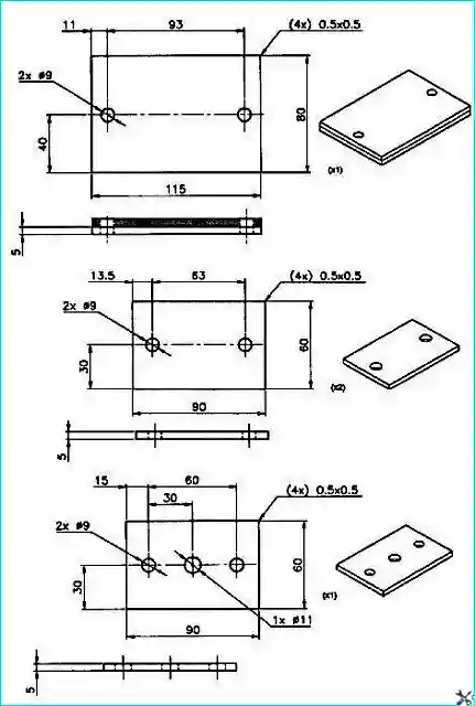
Installing a liquid-oil heat exchanger
To install a heat exchanger you need:
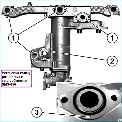
Install rubber rings into the grooves of the holes of the heat exchanger (see Fig. 5):
- - 5 rings (1) Ø 40mm (650.1013642)
- - 1 ring (2) Ø 50.3 mm (650.1013638). Do not reuse rubber rings.
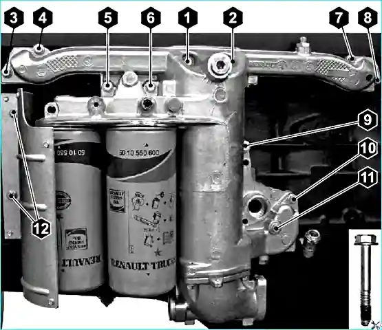
Install two guides for installing the heat exchanger in the threaded holes M8 (6, 7) (see Fig. 7).
Install the heat exchanger on the rails.
Install the bolts (1-5) and (8-11) into the fixing holes of the heat exchanger and screw them into the block by hand (the bolt (11) must be screwed with sealant, as shown in Fig. 7).
Remove the 2 rails and screw the bolts (6, 7) into the freed holes.
Tighten bolts:
- - (1 - 6) M8x1.25-40,
- - (7.8) M8x1.25-25,
- - (9, 10) M8x1.25-40,
- - (11) M8x1.25-60 finally, observing the tightening order (see Fig. 7), torque Mcr = 20 ± 4 Nm.
Check through the special slots (3) (see Fig. 5) the presence of rubber rings.
Install the heat shield on the block on the left side of the filter elements, insert bolts (12) M8x1.25-20 into the screen holes and screw into the block by hand.
Tighten the bolts to the final torque Mcr = 20 ± 4 Nm.
Lubricate the opening of the heat exchanger under the oil drain pipe from the turbocharger and the pipe itself at the place of its installation in the heat exchanger.
Install the oil drain pipe from the turbocharger into the drain hole of the heat exchanger as far as it will go.
Install the retaining plate for the drain tube on the heat exchanger.
Insert the bolt into the hole in the heat exchanger and finally tighten to a torque of Mcr = 20 ± 4 Nm.
Lubricate the ferrules of the oil return pipe to the turbocharger with engine oil.
Install one end of the tube into the turbocharger fitting and screw the union nut onto the fitting.
Insert the other end of the tube into the opening of the heat exchanger fitting and screw the union nut onto the fitting.
Finally tighten both nuts with a torque of Mcr = 24 ± 4.8 Nm.
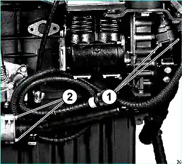
Install the pipe supplying the heat exchanger (see Fig. 6) screw on 2 bolts (1) M8x1.25-16 fastening it to the water pump and 2 bolts (2) M8x1.25-45 to the heat exchanger.
Finally tighten the bolts to Mcr = 27 ± 5.4 Nm.
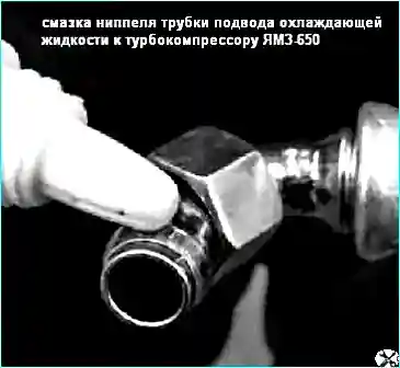
Install the coolant supply pipe between the compressor and the heat exchanger, lubricating the nipples with oil (see Fig. 8).
Screw the union nuts of the nipples onto the fittings and finally tighten them with a torque of Mcr = 25 ± 5 Nm.


