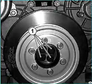
Removing the vibration damper (damper). (See Fig. 1)
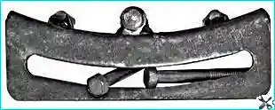
Using a special tool (see Fig. 2), secure the flywheel against rotation.
Unscrew the bolts (1) and remove the damper assembly with the pulley (damper - 650.1005070, crankshaft pulley with flange assembly - 650.1005050).
Removing the damper and crankshaft pulley from the hub. (See Fig. 3)
1. Separate the hub (2) from the damper (3) by unscrewing the screws on the side of the damper.
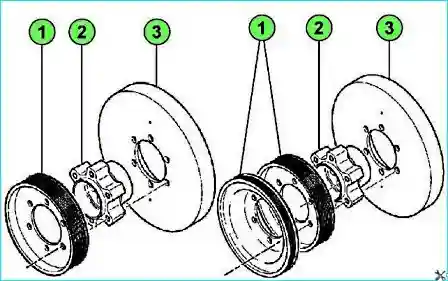
Remove the pulley (1) by unscrewing the bolts securing it to the hub.
Damper control
1. Make sure you don't:
- - beating and ovalization of mounting holes;
- - cracks;
- - traces of blows;
- - low-quality stamping (thickness must be uniform = 3 mm);
- - deformations (on the outer surface);
- - bulges;
- - noise during damper rotation.
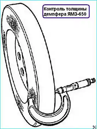
2. Wash off the paint at 4 points on both sides of the damper and measure its thickness at these points (see Fig. 4).
The difference in the measurement results should be no more than 0.25 mm.
If one of the above defects is found, the damper must be replaced with a new one.
The damper must be cleaned before installation.
Installing the damper and crankshaft pulley on the hub (see Fig. 3)
- 1. Assemble hub (2) with damper (3).
- 2. Screw on the damper mounting bolts with washers (the washers are installed with the convex side to the bolt).
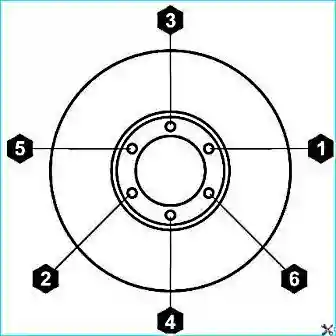
- 3. The damper mounting bolts are tightened in two steps:
- - preliminary Mcr = 50 ± 5 Nm;
- -final tightening Mcr = 120 ± 12 Nm according to the specified order (see Fig. 5).
- 4. Install pulley (1).
- 5. Screw on the pulley mounting bolts and tighten to the recommended torque of 67 ± 7 Nm.
The bolts are installed with Loctite 542 sealant on the threads.
Damper installation
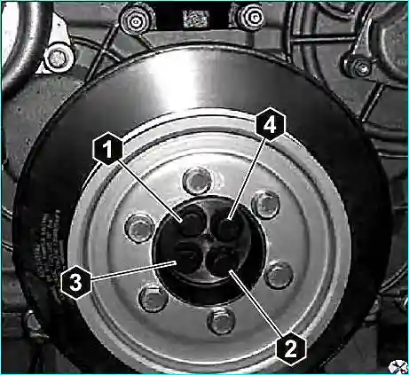
Install the damper in the reverse order of removal.
Tighten the damper mounting bolts to a torque of Mcr = 60 ± 6 Nm and in the order indicated (see Fig. 6).
Additionally check the tightness of the bolt (1). Apply Loctite 542 sealant to the bolt threads.


