Removing the power cylinder from the car
Removal procedure;
- — disconnect the hoses, having first drained the oil from the tank;
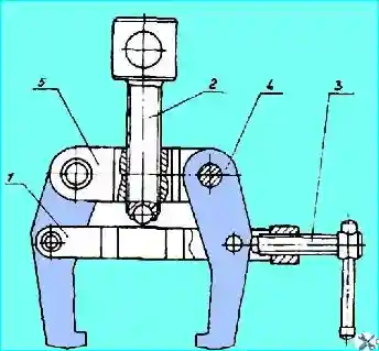
- — unscrew nut 1, plug 19 and press out the ball pin from the longitudinal steering rod using a puller (Fig. 1) as follows:

Fig. 1. Power steering cylinder tip puller: 1 - clamp; 2 - screw; 3 - screw; 4 - grip; 5 - bar
- 1. Unpin and unscrew the power cylinder mounting nut.
- 2. Place the puller grips behind the longitudinal rod tip.
- 3. Secure the grips with the puller clamp screw.
- 4. Rotate the stop screw to remove the cylinder tip:
- — unscrew the nut and remove the lock bolt where the cylinder is attached to the frame bracket;
- — knock out the pin that attaches the cylinder to the frame bracket and remove the cylinder.
Disassembling the cylinder
The disassembly procedure is as follows:
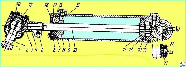
- — secure the cylinder in a vice by the pipe 9 (Fig. 2) closer to the base 14. In order to avoid deformation of the pipe, the clamping force should be insignificant;

Fig. 2. Power cylinder: 1 - nut; 2 - ball pin; 3 - tip; 4 - pin; 5 - tie bolt; 6 - retaining half rings; 7 - sealing ring; 8 - cover; 9 - pipe; 10 - rod; 11 - piston; 12 - sealing ring; 13 - fluoroplastic ring; 14 - base; 15 - wiper; 16 - cuff; 17 - wiper washer; 18 - plate; 19 - plug; 20 - cover; 21 - spherical bearing; 22 - rubber seal; 23 - retaining ring
- — unscrew the bolts and remove the plate 18;
- — move the cover 8 inside the pipe 9 so much as to remove the retaining half rings 6;
- — pull the rod 10 together with the cover 8 out of the housing;
- — remove the piston 11 from the rod, and then the cover;
- — unscrew the nut of the tie bolt 5, knock out the pin 4 and unscrew the rod from the housing of the tip 3.
After disassembling the power cylinder part, carefully inspect it.
There should be no scoring on the working surfaces of the piston and cylinder. Fluoroplastic ring 13 must not have any damage (cracks, tears, etc.).
The working edge of the cuff 16 must not have any tears.
No gaps in the connection of the rod with the tip 3, as well as cracks and burrs on the working surfaces of the spherical bearing are allowed.
Assembling the cylinder
Assemble the cylinder in the following order:
- — screw the rod into the body of the tip 3 and tighten it (tightening torque 98-118 Nm). Install the pin, stake it in the tip body on both sides and tighten the nut of the clamping bolt 5.
When replacing the rod or tip body, drill a hole for the pin:
- — put plate 18, wiper washer 17, cover 8 on the rod and secure the piston on the rod;
- — install the rod in the pipe so that it is possible to insert the locking half rings 6 into the annular groove;
- — secure plate 18 on the cover so that it fits tightly against the pipe hearth. Wiper washer 17 should have some freedom of movement along the rod.
Install the cylinder on the car in the reverse order of removal; fill the system with oil.


