Removing high-pressure pipes
- Unscrew the bolt (12) securing the high-pressure pipe bracket
- Unscrew the union nuts of the high-pressure pipes from the fuel pump, rail and cylinder head
Remove the high-pressure pipes of the supply rail (13) (650.1111673), the rear high-pressure pipes in assembly (14) (650.1112463) and the front high-pressure pipes in assembly (15) (650.1112433).
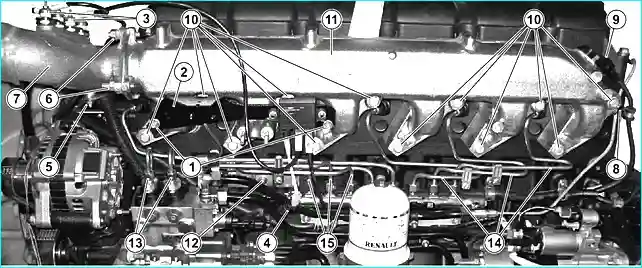
Plug the holes to prevent dirt and dust from getting into the nozzle fittings.
This set of tubes is a non-dismantling assembly. Do not make any changes to the tube bundle under any circumstances, nor change the flange fastening or the tube arrangement.
Removing the low-pressure tubes
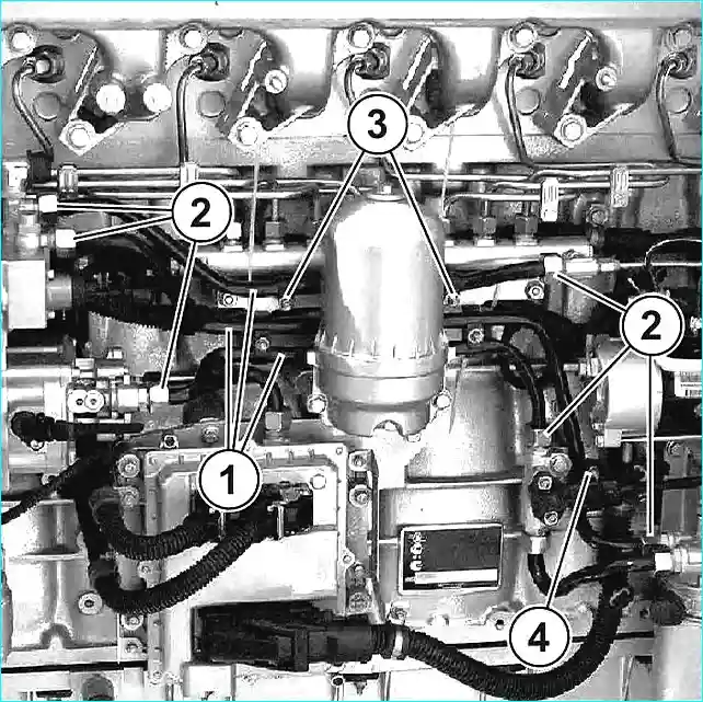
- Unscrew the nuts (3) and the nut (4) securing the low-pressure tubes.
- Unscrew the union nuts (2) of the low-pressure tubes from the rail tee, fuel pump and fuel pressure and temperature sensor housing.
- Remove the low-pressure tubes (1) (650.1104390 - fuel tube outlet ramp, 650.1104525 - tubes from the fuel pump to the fuel filter assembly)
Removing the fuel pump
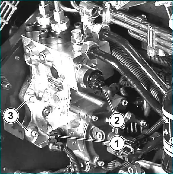
1. Disconnect the connector (1) of the fuel pump camshaft speed sensor (phase sensor) and the connector (2) of the bypass valve.
2. Using tool 1380, set the third cylinder to the top dead center position.
In this position, the key of the fuel pump shaft is turned upward.
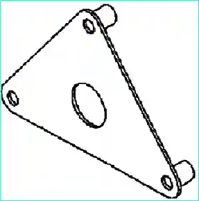
(When removing the fuel pump with the front cover installed, be sure to set the third cylinder to the top dead center position so that the key does not fall into the oil pan, and use tool 2547 to avoid shifting the gear).
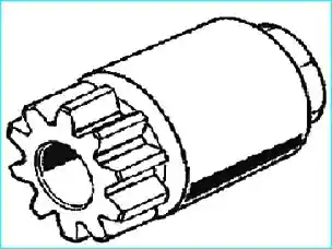
- 3. Remove the nut (650.1111662) securing the fuel pump gear, turn it over and secure it to the gear with the reverse side.
- 4. Using an M14 screw with a screw part length of 60 mm, remove the gear from the fuel pump by screwing it into the nut.
- 5. Unscrew the four nuts (3) (311422) securing the fuel pump.
- 6. Remove the fuel pump (650.1111005).
- 7. Place all parts in an impermeable plastic bag.
Disassembling the fuel pump
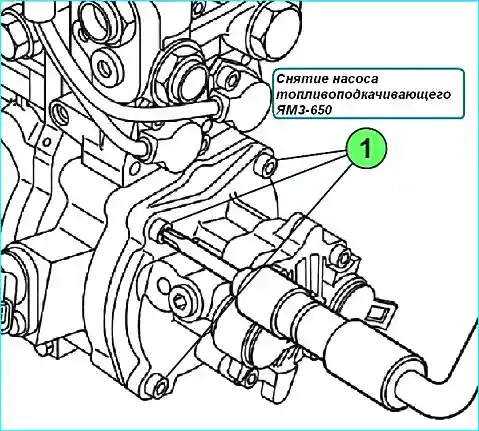
Unscrew the bolts (1).
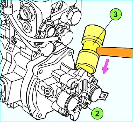
Compress the fuel pump (2) using plastic hammer (3).
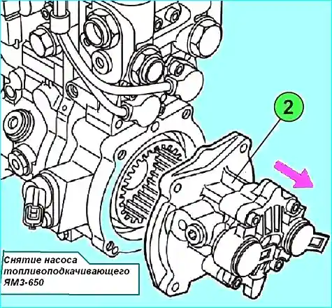
- 3. Remove the fuel pump (2).
- 4. Remove the fuel pump gasket.
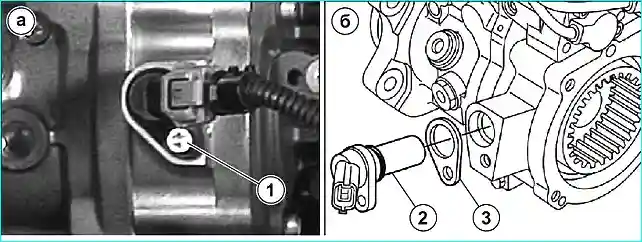
- 5. Loosen the bolt (1) (see Fig. a)
- 6. Remove the phase sensor (2) (see Fig. 6).
- 7. Remove the phase sensor gasket (3)
Assembling the fuel pump
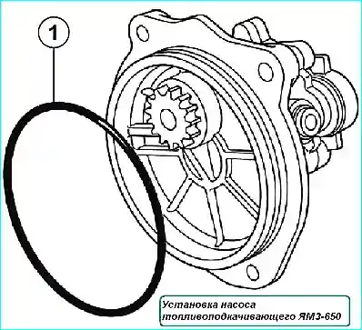
- 1. Replace the seal (1) (see Fig. 1).
- 2. Lubricate the seal (1) with engine oil.
- 3. Center the fuel pump relative to the fuel pump.
- 4. Tighten the fuel pump mounting bolts in a staggered pattern to the recommended torque (see table).
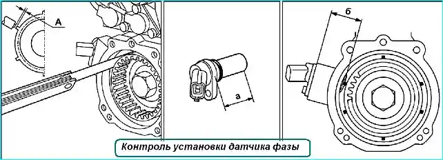
- 5. Lubricate the seal under the sensor with engine oil. Calculate the thickness of the gasket required to ensure a gap of “A” = 0.3 ± 0.1 mm (see Fig. 2):
- - measure the value “a” corresponding to the length of the sensor;
- - measure the value “b” corresponding to the distance from the supporting surface of the sensor to the target of the fuel pump. The thickness of the sensor gasket is 0.3 + “a” - “b” mm.
- 6. Install the phase sensor.
- 7. Screw on the phase sensor mounting bolt and tighten to the recommended torque (see Table 1).
Removing the high-pressure rail
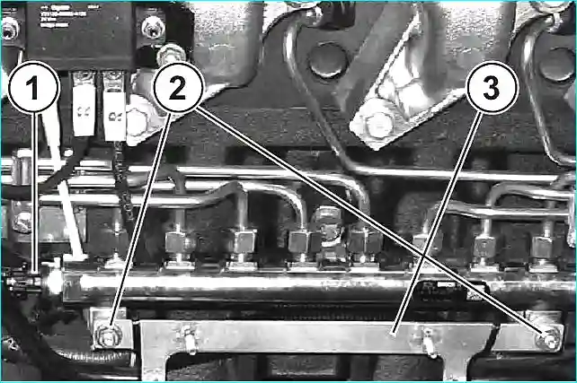
- 1. Disconnect the connector (1) of the pressure sensor in the rail.
- 2. Unscrew the union nut of the fuel drain pipe from the head.
- 3. Unscrew the nuts (2) (311421) securing the rail.
- 4. Remove the bracket (3) (650.1112556) of the low-pressure pipes and the bracket bushings (650.1112554).
- 5. Remove the rail assembly with the pressure sensor and the bypass valve (650.1112552) and the rail bushings (650.1112550)
Disassembling the high-pressure rail
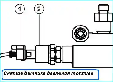
- 1. Unscrew the rail pressure sensor (1), holding the bushing (2).
- 2. Seal the holes.
- 3. After removing, place all parts in an impermeable plastic bag.
Assembling the high-pressure rail
- 1. When installing, proceed in the reverse order of removal.
- 2. Tighten the rail pressure sensor to the recommended torque (see table)
Installing the rail and high-pressure pipes
- 1. Install the high-pressure rail in the reverse order of removal.
- 2. Install the high-pressure pipes, joining their tips with the fittings on the high-pressure fuel pump and the fuel rail, screw on the union nuts of the pipes.
- 3. Install the rear and front high-pressure pipes as an assembly, for which manually install the pipe tips into the corresponding paired holes of the injector fittings and fuel rail fittings, screw on the union nuts. (On new parts, remove the transport plugs immediately before installing them).
- 4. Perform final tightening of high-pressure pipes in the following order:
- - tighten union nuts on fuel supply nipples to injector with torque Мкр = 15 ± 1.5 Nm and tighten further by 60˚ ± 5˚;
- - tighten union nuts on rail with torque Мкр = 25 ± 2.5 Nm and tighten further by 60˚ + 5˚;
- - tighten 2 nuts of rail fastening and bolt of front high-pressure pipe bracket with torque Мкр = 20 ± 4 Nm;
- - tighten nuts of pipes on fuel pump with torque Мкр = 15 ± 1.5 Nm and tighten further by 60˚ ± 5˚.
- 5. Tighten the union nut of the fuel drain pipe from the head with a torque of Mkr = 28 ± 2 Nm.
Tightening torques of the fuel injection system YaMZ-650
- Fuel pump mounting studs - (Loctite 542 sealant) 20 ± 4 Nm
- Bolts for mounting the booster pump - (tighten in a staggered pattern) 8 ± 1 Nm
- Bolt for mounting the fuel pump shaft speed sensor (phase sensor) 8 ± 1 Nm
- Screws for mounting the air pressure and temperature sensor in the intake manifold 6.5 ± 1.5 Nm
- Nuts for mounting the fuel lines to the rail and the injector nipple - 40 Nm (in case of fuel leakage, tighten to the maximum torque of 50 Nm)
- Rail pressure sensor 20±2 Nm
- Bushing connecting the pressure sensor to the rail 45±5 Nm
- Nuts for fastening low-pressure polyamide pipes 28±2 Nm
- Fuel pump oil filler plug 35±5 Nm
- Screws for fastening the wiring harnesses of the engine sensors 30±6 Nm
- Nut of the injector fitting in the cylinder head - preliminary tightening torque of 5 Nm; final tightening torque 60 Nm
- Fuel pump drive gear fastening nut 195±20 Nm
- Fuel pump fastening nuts - (tighten crosswise and then tighten only the nut that was tightened first) — 60±12 Nm


