The springs are made of strip spring steel (T-shaped profile) grade 60S2
The spring leaves are heat treated (hardened, tempered) to a hardness of HBZ6Z-444
All springs have leaves pulled together in the center with a center bolt.
To prevent the spring leaves from diverging to the sides, they are pulled together with clamps.
The ears of the clamps are pulled together with bolts.
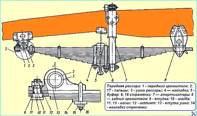
The front suspension design is shown in Fig. 1.
The front springs are installed on special platforms of the front axle beam and attached to it with U-bolts made of 40X steel

The front spring is attached to the frame using a removable overlay eye 3, which is connected to the main leaf with a special stepped pin 17, and to the spring bracket with a spring pin.
To prevent the pin from turning and moving longitudinally, the bracket has chamfers at its ends, one of which contains a bolt that tightens the split part of the bracket.
There is a gap of 0.3 - 1.25 mm between the head of the stepped pin of the overlay eye and the main leaf, which is necessary for moving the main leaf in the longitudinal direction when the spring is operating.
The rear end of the overlay eye is attached using a step ladder 16 and overlay 14, fixed to the end of the fourth leaf.
To protect rear spring bracket from intensive wear due to sliding of spring ends on the support surface and side walls, replaceable protective liners are attached to its inner surface.
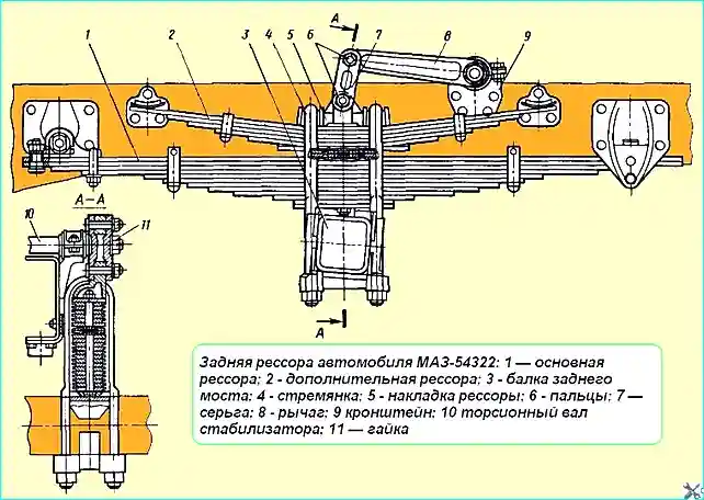
The main rear spring 1 and additional 2 of the MAZ-54322 vehicle (Fig. 2) are attached with U-bolts 4 to the rear axle beam.
The additional spring is placed on top of the main one, and spacers are installed between them.
The fastening of the front and rear ends of the main rear spring to the frame is carried out in the same way as the fastening of the front one.
The additional rear spring has straight ends and rests on the sliding supports of the frame brackets. The pushing forces from the rear axle to the frame are transmitted by the front end of the main spring.

When manufacturing, the springs are divided into two groups depending on the deflection arrow and when installed on a vehicle, they are selected so that the difference in the deflection arrow for the left and right springs does not exceed 8 mm.
The rear suspension of the MAZ-54322 vehicle is equipped with an anti-roll bar, which increases the stability of the vehicle when driving on roads with a lateral slope and on turns.
The elastic element of the stabilizer is the torsion shaft 10.

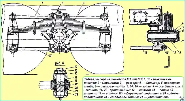
The rear suspension of the MAZ-64227 vehicle (Fig. 3) is of the balance beam type. The ends of the springs 3 rest freely on special supports that protect the drive axle beams from wear.
The middles of the springs are attached with stirrups 2 to the balance beams 4, which can swing on the axles 8 of the balance suspension.
The axles 8 are pressed into brackets 9, which are bolted to the vehicle frame.
Both drive axles are pivotally connected to the frame using a system consisting of six reaction rods that absorb the forces from the reaction and braking moments and transmit pushing forces.
Spring maintenance
Spring maintenance consists of lubricating the spring fastening pins in the brackets, checking the spring fastening, lubricating the spring leaves, and checking the fastening of the rear spring bracket liners.
Longitudinal mutual shift of the leaves may indicate the center bolt, so it is necessary to check the relative position of the spring leaves in a timely manner.
To avoid The spring U-bolts should be tightened without the central bolts, and they are tightened only when the springs are straightened.
The tightening torque of the U-bolt nuts of the front springs is 40-45 kgcm, and of the rear springs (MAZ-54322) - 60-64 kgcm.
If a creaking sound appears, the springs must be lubricated with graphite grease. To do this, lift the vehicle by the frame, release the springs and separate the sheets.
Add graphite grease into the gaps between the sheets.
Maintenance of the rear suspension of the MAZ-64227 vehicle comes down to checking the tightening of all bolted connections.

Special attention should be paid to the fastening of brackets 11 (see Fig. 3) to the vehicle frame and the tightening of the U-bolts, as well as the connection of the joints of the reaction rods and nuts 10 fastening the coupler 12.
The tightening of the U-bolt nuts of the rear springs should be done on an unloaded vehicle, the tightening torque is 70 - 80 kgcm.
The tightening torque of nuts 10 is 32 - 40 kgcm, and the bolts for fastening the brackets of the reaction rods 18 - 20 kgcm.
During seasonal maintenance, it is necessary to change the oil in the balancer housing, for which it is necessary to remove the balancer cover, drain the oil, wash the cover and install it in place.
Pour clean oil up to the level of the filler hole. During operation, it is necessary to ensure that there is no grease leakage through the covers and the oil seal of the balance shaft.
Leaks are eliminated by replacing the oil seals, balance shaft cover gaskets and tightening the cover mounting bolts.
Spring repair
Before starting to remove the spring, you need to brake the car with the parking brake, install wheel stops, loosen the wheel mounting nuts and spring U-bolts.
The procedure for removing the front and rear (MAZ-54322) springs is as follows:
- - unload the wheel on the side of the spring being removed with a jack and install a stand under the frame side member;
- - remove the wheel, disconnect and remove the shock absorber (for the front suspension);
- - unscrew the U-bolt nuts spring mounts, place pads under the drum and, lowering the jack, release the beam from the spring until the drum is seated on the pad;
- - remove the spring pin mount wedge, knock out the pin, remove the eye from the front bracket and remove the spring.
To restore a broken spring, it must be disassembled in order to replace the broken sheet. When assembling the spring, the nuts of the U-bolt fastening the overhead eye are tightened with a torque of 2 - 4 kgfm and punched at two opposite points.
In the fastening of the front end of the spring, the pins and bushings are subject to the greatest wear. The pins and bushings are replaced if the gap in the joint is more than 2 mm.
In the fastening of the rear end of the spring, the upper and side liners are subject to the greatest wear, which are replaced as they wear out. If they are not replaced in a timely manner, the walls of the brackets wear out.
If the walls are worn out by more than 2 mm in thickness, the brackets must also be replaced.
Attention should be paid to the uniformity of the shrinkage of the right and left springs. If the difference in shrinkage of the left and right springs on a loaded vehicle is more than 15 mm, then the spring with greater shrinkage is replaced.
Spring brackets are subject to replacement if cracks or breaks are detected (welding is not allowed), as well as if the holes for rivets are worn.
If the holes for rivets are slightly worn, temporary fastening of the brackets to the frame with bolts is allowed; the holes for the bolts are first reamed to the required size.
Spring assembly is also performed on a device with a screw or hydraulic clamp. Before assembly, the spring leaves must be lubricated with graphite grease, assembled and tightened with a center bolt.
The springs are installed on the vehicle in the reverse order of removal.
Repair of the rear suspension of the MAZ-64227 vehicle
The procedure for removing the rear suspension is as follows:
- - disconnect the cardan shafts from the middle and rear axles;
- - disconnect the pneumatic system pipes going to the axles;
- - knock out the pins of the upper reaction rods 1 (see Fig. 3), having first unscrewed the nuts, and remove the rods;
- - unscrew the bolts securing the balancer brackets 4 to the frame;
- - lift the rear of the vehicle by the frame with a lifting device and roll out the axle bogie from under car frames.
The upper brackets of the reaction rods on the axle gearbox housings must be tied together with wire y, so that during the rolling of the bogie the bridges do not tip over and do not come out from under the springs;
- - put the rear part of the car frame on trestles.
The rear bogie must be disassembled in the following order:
- - unscrew the nuts of the U-bolts 2;
- - supporting the axle 8 of the balance beams with a lifting device so that it does not fall, remove the U-bolts of the springs;
- - remove the springs;
- - unscrew the nuts of the pins of the lower reaction rods, knock out the pins and remove the rods 13;
- - roll back the rear and middle axles; remove balancer covers, drain oil, unscrew nut 7, remove lock 6 and lock 5 washers, unscrew ring nuts and remove balancers assembled with bushings and seals.
Broken or cracked spring leaves, broken center bolts and clamps are subject to replacement. Cracks on clamps may be welded and cleaned flush with the main surface.
The first main leaves with a wear thickness of more than 4 mm are swapped with the second spring leaves.
Main leaves with a wear thickness of more than 6 mm are replaced with new ones. Sheets with residual deformation (sagged) are straightened.
Spring mounting bolts with cracks or stripped threads are replaced with new ones.
Before assembly, spring sheets are lubricated with graphite grease, assembled and the spring is tightened with a center bolt.
Bushes and seals of the balancers, pins of the reaction rods, worn out during operation, are subject to replacement.
The rear suspension is installed on the car in the reverse order of removal.


