The vehicles are equipped with a windshield wiper with three brushes for cleaning the windshields
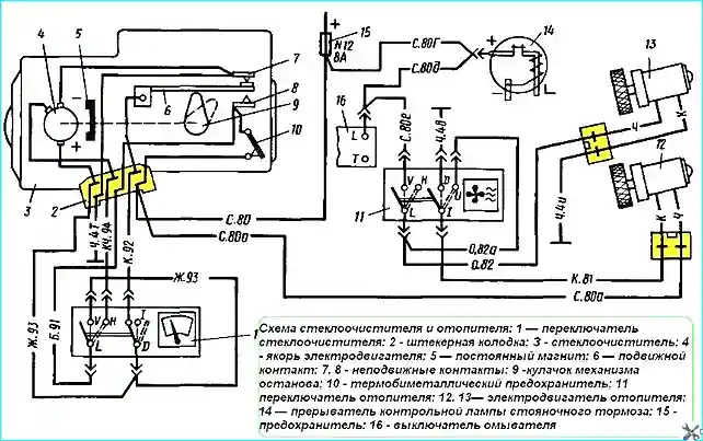
The windshield wiper is switched on by switch 1 (Fig. 1), which has three positions:
«Off», «Low speed on», «High speed on».

When the first (low) speed is turned on, contacts "L" and "V" are turned on, as well as "D" and "I" of switch 1.
Voltage is supplied via the gray wire to the thermal bimetallic fuse 10 and from it to the fixed contact 8. Then the current goes to the plug-in block and from it via the white wire to the "L" terminal of the switch.
From the "L" terminal, the current goes to the "V" terminal, via the yellow wire goes to the "D" terminal, and through the plug-in block to the positive electric brush of the electric motor armature.
After passing through the armature, the working current goes to the fixed contact 7 and from it via the plug-in block via the black wire goes to mass.
Due to the interaction of the magnetic fields of the permanent magnet 5 and the magnetic field of the anchor, the latter begins to rotate.
At the same time, the cam 9, mounted on the worm gear of the windshield wiper gearbox, rotates, closing and opening contacts 6, 7 and 8.

When the second, high speed is turned on, the contacts of terminals "L" and "H" of switch 1 are closed, the contacts of terminals "D" and "I" are opened, the working current no longer goes to the positive terminal of the armature, but through the brown wire to the additional electric brush, which leads to a decrease in the working turns of the armature and, consequently, to a decrease in the magnetic field of the armature, as a result of which the rotation speed of the armature increases.
When the windshield wiper is turned off, the circuit of terminals "L" and "V" of switch 1 is broken, but armature 4 of the electric motor continues to rotate, since power is supplied to it through closed contacts 6 and 8 to the plug block, from it through the red wire to switch 1, through it - to terminal "D", from which the current passes through the yellow wire to the positive electric brush of the armature, through the armature - to the negative brush, to contact 7 and from it to ground.
The anchor rotates until cam 9 opens contacts 6 and 8. This position of the cam corresponds to the placement of the windshield wiper blades at the bottom of the car windshield.
Due to the inertia of the anchor, the latter can make several more revolutions before stopping, which will lead to the brushes moving up the windshield, which will interfere with the driver.
In order to eliminate this phenomenon, contact 7 was introduced, when it is closed with contact 6, the anchor electric brushes are shunted between themselves, which is easy to follow in the diagram.
When shunting, the anchor stops abruptly, which ensures that the brushes are laid strictly in a given position.
Two electric motors are installed in the cabin heating and ventilation system, which are switched on at low and high speeds, which changes the performance of the fans.
In the first position switch 11, both electric motors operate at high speed, since they are connected in parallel. In the second position, both electric motors are connected in series.
Windshield wiper maintenance
Windshield wiper and heating system electric motors are not subject to maintenance during operation.
Possible windshield wiper malfunctions and troubleshooting methods
- Cause of malfunction - Troubleshooting method
Windshield wiper does not work:
- - Fuse No. 12 has blown - Replace the fuse
- - Circuit malfunction - Check the circuits according to the diagram. Fix the problem
- - Worn out electric brushes - Disassemble the electric motor and replace the electric brushes
The windshield wiper blades do not stop in the lower position:
- - The lever system is not installed correctly - Install the rods in accordance with the drawing
- - The stop system contacts are faulty - Remove the windshield wiper, inspect the contacts and repair
The windshield wiper works intermittently:
- - O the nut on the windshield wiper arm drive shaft is loose - Tighten nut 8 (see Figure 2)
If the windshield wiper fails to operate, first make sure that fuse #12 is in good condition and that there is voltage on the gray wire in the windshield wiper plug.
If there is voltage on the wire, then check the condition of fuse 10 (see Figure 1), installed on the windshield wiper housing. If there is voltage there, then check the condition of switch 1.
After making sure that the switch is in good condition, the windshield wiper must be removed and repaired.
Repair
After disassembling the windshield wiper, inspect the anchor, electric brushes, contact system of the stop mechanism, and the worm gear of the gearbox.
If the teeth of the wheel are worn out, it is replaced with a new one. The contacts of the stop mechanism are cleaned.
The electric brushes are replaced with new ones when worn.
The anchor is inspected and, if necessary, the collector is turned and ground.
When installing the windshield wiper on a car after repair or when installing a new windshield wiper, the lever system should be installed as shown in the figure, i.e. stretched out in one line.
Failure to comply with this rule will lead to disruption of the windshield wiper or its failure.


