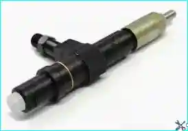
The injector is designed to inject fuel into the engine combustion chamber in a finely atomized state.
The engine is equipped with closed-type injectors with a multi-hole sprayer and a hydraulically controlled needle.
The injectors are located in the cylinder head (in brass cups) opposite each cylinder between the valves and are secured with a bracket.
The end of the injector sprayer enters the combustion chamber.

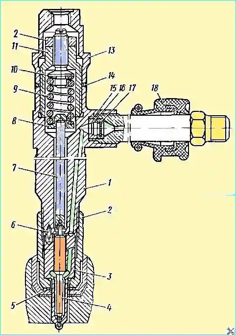
The main parts of the injector sprayer 3 with needle 4, spring 9 and adjusting screw 10 are mounted in body 1 of the injector.
The body of the sprayer 3, inside which the shut-off needle is located, is attached to the lower end of the body of the injector with a nut 2.
The seal between the ends of the bodies of the sprayer and the injector is achieved by careful processing of these surfaces with subsequent lapping without additional sealing parts.
Just like the plunger pair and the discharge valve of the fuel pump, the sprayer with the needle are selected in pairs, and their disassembly during operation is not allowed.

Fig. 2. Injector: 1 - injector body; 2 - atomizer nut; 3 - atomizer; 4 - atomizer needle; 5 - sealing washer; 6 - pin; 7 - rod; 8 - spring plate; 9 - spring; 10 - adjusting screw; 11 - spring nut; 12 - adjusting screw lock nut; 13 - cap; 14 - sealing washer; 15 - nipple; 16 - bushing; 17 - filter; 18 - nozzle seal
There are four nozzle holes in the lower part of the atomizer body through which fuel is injected into the combustion chamber.
The inner hole of the atomizer body at the bottom turns into a cone, which serves as a seat for the sealing cone of the needle.
The atomizer is fixed relative to the nozzle body with two pins 6.
A nut 11 is screwed into the upper part of the nozzle body, onto which a cap 13 with a sealing washer 14 is screwed.
An adjusting screw 10 is screwed into the nut from below, resting with its shoulders on spring 9. The other end of the spring through plate 9 presses on rod 7, which with its lower end with a ball presses the needle to the nozzle seat, closing the outlet.
The pre-tightening force of the spring is adjusted by the screw 10, secured with lock nut 12.
A nipple 15 is screwed into the side of the housing on the thread, through which fuel is supplied to the injector.
At the end of the nipple, a mesh filter 17 is installed for the final cleaning of the fuel before it reaches the needle.
Rubber seal 18 on the nipple serves to seal the space of the cylinder head where the nipple is covered by the head cover.
A copper corrugated washer is placed under the end of the nozzle nut to prevent gas breakthrough.

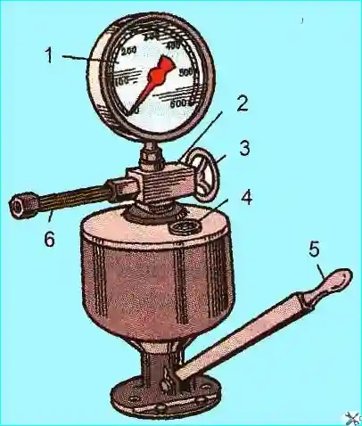
Fig. 3. Device for testing and adjusting the injector: 1 - pressure gauge; 2 - shut-off valve; 3 - flywheel for disabling the pressure gauge; 4 - fuel level indicator; 5 - priming pump handle; 6 - high-pressure tube for connecting the injector
Checking and adjusting the injectors
After one TO-2, the injectors must be removed from the engine and the pressure at which the needle begins to lift and the quality of fuel atomization must be checked. This work is best performed on the KI-EZEZ device.
The pressure at which the needle begins to lift must be 200 +15 kgf/cm². To adjust the injector to this pressure, it is necessary to:
- - unscrew and remove the injector cap; loosen the lock nut of the adjusting screw;
- - using the lever of the device, slowly increase the fuel pressure in the injector cavity and, observing the pressure gauge readings, determine the pressure at which the needle begins to rise, at which fuel injection begins;
- - using the adjusting screw, set the required pressure at which the needle begins to rise (when the screw is screwed in, the pressure increases, when unscrewed, it decreases);
- - tighten the lock nut of the adjusting screw and check the pressure at which the needle begins to rise again.
The quality of fuel atomization by the injector is checked by moving the lever of the device at a rate of approximately 70-80 strokes per minute.
It is considered satisfactory if the fuel is injected into the atmosphere in a misty state and is evenly distributed over the cross-section of the jet cone and over each hole of the atomizer.
The beginning and end of the injection must be clear.
Fuel injection by a new injector is accompanied by a characteristic sharp sound.
The absence of a sharp sound in used injectors when checking them on a manual stand does not serve as a sign that determines the poor performance of the injector.
Injector repair

Fig. 2. Injector: 1 - injector body; 2 - nozzle nut; 3 - nozzle; 4 - nozzle needle; 5 - sealing washer; 6 - pin; 7 - rod; 8 - spring plate; 9 - spring; 10 - adjusting screw; 11 - spring nut; 12 - adjusting screw lock nut; 13 - cap; 14 - sealing washer; 15 - nipple; 16 - bushing; 17 - filter; 18 - nozzle seal
The nozzle must be disassembled on the device in the following order:
- - unscrew the cap 13 of the nozzle;
- - loosen the lock nut 12 and unscrew the adjusting screw 10 until it stops;
- - unscrew the nut 11 of the spring, remove the spring 9 and the rod 7 of the nozzle;
- - unscrew the nut 2 of the sprayer; remove the sprayer 3, securing the sprayer needle 4 from falling out, in order to avoid damage to the locking pins 6, it is not allowed to remove the sprayer nut without first unscrewing the adjusting screw 10 and the spring nut 11;
- - unscrew the nozzle nipple 15.
The sprayer parts must be cleaned of carbon deposits and washed in kerosene.
The carbon deposits on the outer surface of the sprayer are cleaned with a brass brush, and the nozzle holes are cleaned with a steel wire with a diameter of 0.3 mm.
The sprayer supply channels are cleaned manually with a drill with a diameter of 2 mm.
The internal cavities of the sprayer are cleaned of carbon deposits with brass scrapers, the sharp end of the needle with a brass brush.
Use for cleaning the sprayer sharp and hard objects, sandpaper or rags are not allowed.
Special attention should be paid to the condition of the nozzle sprayer.
Its main parameters are checked on the assembled nozzle, but before installing it on the nozzle, the condition of the surface of the needle and the sprayer body should be checked.
The sprayer body with traces of melting of the nose and with a noticeable increase and ellipticity of the nozzle holes is rejected.
Scratches and traces of wear on the end surface of the sprayer body are removed by lapping on plates and finishing to a mirror shine.
If there are matte spots or traces of overheating on the surface of the guide part of the needle, as well as scratches and scratches, the sprayer is replaced with a new one.
The sprayer needle should move smoothly, without jamming or seizing.
The needle (after thoroughly washing the parts sprayer in kerosene and lubrication with clean diesel fuel), extended by ⅓ of the length of the guide surface from the housing at an angle of inclination of the sprayer axis of 45 °, should smoothly, without jamming, lower to the stop under its own weight.
The nozzle housing may have the following defects: scores, scratches and traces of corrosion on the end surface from the sprayer side, broken threaded connections, mechanical damage and contamination of the fuel channels.
If there are scores, scratches and traces of corrosion on the end surface, the nozzle housing is replaced.
A housing with damaged threads or with rough mechanical damage is also replaced.
The holes and channels in the housing are cleaned in a bath of kerosene with hair brushes, and the outer surfaces are cleaned with soft metal brushes.
The nipple, cap, nuts, springs and spray nozzles with crushed or torn threads are replaced.
It is recommended to blow out the injector filters with compressed air at a pressure of 5-7 kgf/cm², in the direction opposite to the fuel flow.
The injector is assembled in the reverse order of disassembly. In this case, it is necessary to pay attention to the following:
- - before assembly, all parts of the injector must be thoroughly washed in clean kerosene and lubricated with filtered diesel fuel;
- - install the sprayer before installing the injector spring;
- - tighten the sprayer nut when installing the sprayer assembly on the injector body with a torque of 7-8 kgfm;
when screwing on the nut, turn the sprayer against the direction of screwing the nut until it stops in the locking pins and, holding it in this position, screw the nut by hand, then tighten it completely.
- - After tightening the nut, check the ease of movement of the needle: when shaking the injector, you should hear the impact of the sprayer needle on the injector body;
- - tighten the nipple when installing in the injector body, apply a torque of 8-10 kgf m, tighten the spring nut - 10-12 kgf cm; tighten the injector cap - 8-10 kgf cm.
Injectors on which previously used sprayers are installed must be tested for tightness in the needle-sprayer body connection, for the tightness of the cones and the quality of fuel atomization.
The density is checked by tightening the injector spring until the start of injection of 300 kgf/cm².
The time for the pressure to drop from 280 to 230 kgf/cm² must be at least 2 s, viscosity 1.4-1.5 conventional units at a fuel temperature of 1 during the test period 8-22 °C.
Fuel leakage along the sealing cone and seepage along the thread of the nozzle nut are not allowed.
After checking for tightness, set the nominal injection start pressure to 200 +15 kgf/cm², check the tightness of the shut-off cone and the quality of fuel atomization by the injector.
The tightness of the shut-off cone of the atomizer is determined by the degree of moistening of the atomizer nose while maintaining the pressure in the injector 10 kgf/cm² below the injection start pressure for 1 min.
The atomizer is unsuitable for further use if 3 drops per minute are formed and detached from the nose.
The quality of fuel atomization is checked at 90 - 120 injections per minute and nominal fuel supply.
The atomized fuel should be in a foggy state. The start and end of injection should be accompanied by a sharp sound.
If the specified conditions are not met, the nozzle must be removed from the injector and cleaned of carbon deposits or replaced with a new one.
The injectors on which the nozzles taken from spare parts are installed must be run-in on a special stand.
Tests are carried out on filtered summer diesel fuel at an injection pressure of 185 kgf/cm².
The injection pressure is adjusted by screw 10, when screwed in, the pressure increases, when unscrewed, it decreases.
After adjustment, the screw must be securely locked with a lock nut.
The injectors are run-in for 20 minutes with their connection to the fuel injection pump.
The stand pump must be adjusted to a cyclic feed of 120 mm³ at a rotation speed of camshaft 1050 min, the pump rack must be fixed in a constant position.
After finishing the running-in tests, the injector must be checked for density, fuel atomization quality and tightness.
After setting the fuel injection start pressure to 200 +15 kgf/cm², it is necessary to check the fuel atomization quality; the atomized fuel at 40-50 injections per minute must be in a fog-like state, without noticeable individual drops, local condensations and continuous streams.
The start and end of the injection must be clear and accompanied by a sharp sound.
Fuel passing through the shut-off cone of the needle at a pressure of up to 185 kgf/cm² is not allowed.
With a further continuous increase in pressure before injection, the appearance of a drop that does not come off the nozzle tip is allowed.


