Control diagnostics of the MAZ air suspension system using flashing light codes
If difficulties arise in determining the malfunction, it is necessary to carry out a diagnostic check of the system using flashing light codes
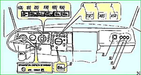
To carry out a check of the system using flashing light codes, it is necessary to move the starter and instrument switch to the "instruments" position and switch the electronic unit to diagnostic mode by pressing button 14 (Fig. 1).

Fig. 1. Location of ABS and air suspension control system indicator lights and components on the instrument panel: 1 - tractor ABS indicator light; 2 - trailer ABS indicator light; 3 - trailer ABS power supply circuit indicator light; 4 - ABS mode and ABS/PBS diagnostics indicator light; 5 - ABS operation mode switch; 6 - "Temposet" mode switch (only for vehicles equipped with a speed limiting device); 7 - PBS mode switch (only for vehicles with PBS); 9 - suspension transport position indicator light; 10 - ISO 9141 connector; 12 - vehicle ABS diagnostics button; 13 - trailer ABS diagnostics button; 14 - air suspension control system diagnostics button
After 3 sec. after releasing the button, the first light code is issued in the form of two series of blinks (flashes) of the red control lamp 8.
In the first series, the light code is transmitted by light pulses lasting 2 sec., in the second series - 0.5 sec., the pause between pulses is 1 sec. between series 3 sec.
To read the code of the next error or malfunction, press button 14 again, as described above.
The malfunction codes are issued in the order of increasing number of light pulses (flashes) in the first series.
In this case, the number of blinks of the control lamp in the first series of light flashes indicates the location of the malfunction, and in the second series - the type of malfunction.
The light code of a fully functional system is 0-0, i.e. after pressing and releasing button 14, the control lamp 8 (Fig. 1) will not blink.
The light codes of the main malfunctions are given in Table 1.
To erase the error codes or malfunctions from the memory of the electronic unit after troubleshooting, it is necessary to:
- - switch the starter and instrument switch to the "0" position ("off");
- — press button 14 (Fig. 1);
- — switch the starter and instrument switch to the "instruments" position and release the button within 2-4 seconds.
After this, switch the starter switch to the "off" position.
If not all faults were eliminated before erasing the error codes from the memory of the electronic unit, then when the switch is turned on again to the "instruments" position, the codes of the remaining errors will be recorded again in the unit's memory and can be called up in the diagnostic mode, as described above.
If the red indicator lamp does not go out after turning on the power and you cannot fix the fault yourself using the tables, you should contact a service station or warranty point.
Before starting to check the system, it is necessary to check the serviceability of the standard electrical equipment, pneumatic system and fuses of the air suspension system power supply.
On-board network voltage and the pressure in the pneumatic system must correspond to the nominal values, the fuse links must be intact and correspond to the nominal value.
When replacing a fuse, be sure to use a fuse of the same rating!
Change fuses, indicator lamps and disconnect/connect cables and other switching devices only with the power supply (battery) disconnected from the vehicle.
Light codes for possible malfunctions of the electronic air suspension control system
Error number - Faulty system element - Nature of malfunction
- 0-0 - System is in good working order
- 0-1-6 - Control unit - Calibration error or malfunction of the electronic unit
- 1-0-2 - Position sensor - Open or short circuit to positive on-board network
- 1-4-6 - Position sensor - Short circuit to ground on-board network
- 2-0-4 - Valve block - Open or short circuit to positive of on-board network
- 3-0-4 - Valve block - Short circuit to ground of on-board network
- 4-0-2 - Position sensor - Inadmissible signal value when lifting
- 4-4-6 - Position sensor - Inadmissible signal value when lowering
Electronic system fuses
Item number – Purpose - Pos. - Rating, A
- 1 - Power supply for the trailer system from terminal 30 of the 2101.370400-11 lock - FU1 - 16
- 2 - Reserve for the EDC type system - FU2 - 8
- 3 - Power supply for the modulators to wheels B, C of the tractor from terminal 30 of the lock 2101.370400-11 - FU3 - 8
- 4 - Power supply for the modulators of wheels A, D of the tractor from terminal 30 of the lock 2101.370400-11 - FU4 - 8
- 5 - Power supply for the diagnostic equipment from terminal 30 of the lock 2101.370400-11 - FU5 - 8
- 6 - Reserve for the ECAS system - FU6 - 8
- 7 - Reserve for the ECAS system - FU7 - 8
- 8 - Power supply for the ABS control lamps of the tractor and the ABS system of the semi-trailer - FU8 - 8
- 9 - Power supply for the ABS info module of the semi-trailer from terminal 15 of lock 2101.370400-11 - FU9 – 8
- 10 - Power supply of the tractor's ABS electronic unit system from terminal 15 of lock 2101.370400-11 - FU10 - 8


