The cylinder head is a single casting made of gray cast iron and is attached to the block with studs screwed into the block.
The studs are made of chromium-nickel steel and heat-treated.
To ensure heat dissipation, the cylinder head has a water jacket communicating with the block jacket; to ensure fuel supply to the injector, there are holes for the nozzles in the side surface.
The cylinder head contains valves with springs and their fastening parts, rocker arms, rocker arm shafts and injectors.
The valve seats are inserted.
The inlet valve seats are made of special cast iron, and the exhaust valve seats are made of a special heat-resistant alloy.
The seats are pressed into the sockets with by tension.
The valve seats and metal-ceramic guide bushings are finally processed after they are pressed into the head.
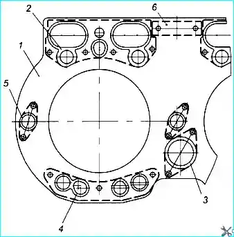
The cylinder heads installed on the engines have design differences:
The cylinder heads on the YaMZ-236NE2,BE2 engines can be block-type for three cylinders each or individual:
- — Block head for three cylinders each. The mating surface is ground and annular grooves are made in the sealing area of the cylinder liners.
The joint of the cylinder head, block and liner is sealed with a gasket consisting of a single metal gasket for three cylinders, sealing the gas joint, and rubber sealing elements sealing the oil, water and rod cavities.
Sealing elements of five types in the amount of 14 pcs. on the gasket (Fig. 1).
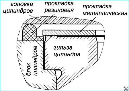
An individual head is installed on each cylinder and is attached to the block with six studs, 209 mm and 248 mm long.
A cast iron nozzle cup is pressed into the head.
The cup is sealed at the top with a rubber ring.
The mating surface in the sealing zone of the cylinder liners has three annular grooves.
The joint of the cylinder head, block and cylinder liner (Fig. 2) is sealed with a gasket consisting of a metal gasket, sealing the gas joint, and a rubber gasket sealing the oil, water and rod cavities.
The metal and rubber gaskets are installed on the block pins.
The metal gasket is available in four thicknesses (1.1 mm; 1.3 mm; 1.5 mm; 1.7 mm) and is selected during engine assembly individually in order to achieve the optimal working process in each cylinder.
A 1.7 mm thick gasket is supplied as spare parts.
The cylinder heads on the YaMZ-236N; (B; NE; BE) engines are block-type, with three cylinders each. Structurally, it is made basically similar to the previous block.
Remove the cylinder head only to troubleshoot the cylinder-piston group parts, cylinder head gasket, valves, or to replace the head itself.
Remove the cylinder head in the following order:
- 1. Drain the coolant from the engine cooling system.
- 2. Disconnect all pipes from the head, protect their internal cavities from dust and dirt.
- 3. Remove the cylinder head cover.
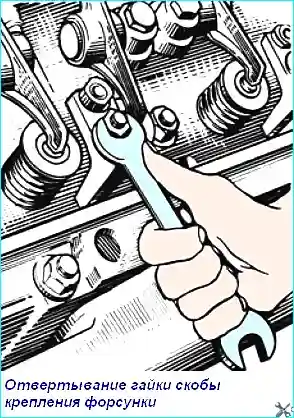
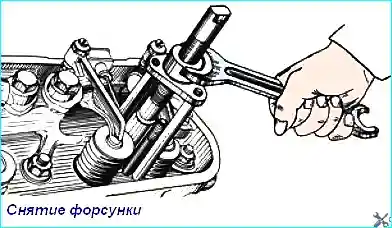
- 4. Unscrew the injector mounting bracket nuts (Fig. 3), remove the injectors (Fig. 4), protecting the sprayer from impacts and clogging of the holes
- 5. Loosen the rocker arm axle mounting nuts, remove the rocker arm axles together with the rocker arms and remove the rods.
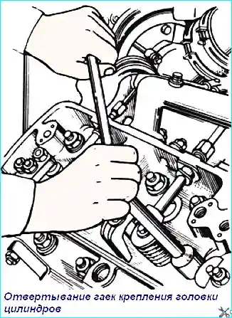
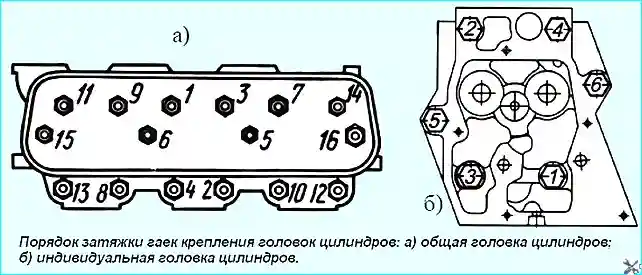
6. Loosen the cylinder head mounting nuts (Fig. 5), following the sequence reverse to tightening (Fig. 6).
Unscrew the fastening nuts of individual cylinder heads in at least three steps:
- 1 – step - up to 147...118 Nm (15...12 kgf/cm)
- 2 – step - up to 49...39 Nm (5...4 kgf/cm)
- 3 – step - unscrew the nuts.
- 7. Remove the cylinder head from the engine and inspect its condition.
- 8. If necessary, carefully remove the cylinder head gasket.
- 9. Check the condition of the cylinder liners and close the cylinder holes to protect them from dust and dirt.
Install the cylinder head on the engine in the reverse order.
Before installation, wipe the mating surfaces of the cylinder block, the flange of the cylinder liner and the cylinder head with a clean rag.
Reusing the cylinder head gasket is allowed with the same cylinder head only if the position of the liners in the cylinder block is unchanged and there are no signs of gas breakthrough or destruction of the edges of the gas joint.
Pay attention to the correct installation of the cylinder head gasket on the pins and the edges of the gaskets - on the flanges of the cylinder liners.
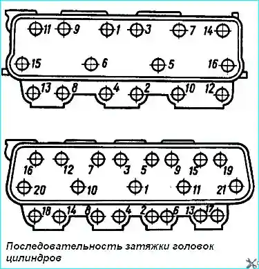
Tighten the cylinder head fastening nuts in ascending order of numbers, as shown in Fig. 7, to a torque of 240 - 260 Nm (24 - 26 kgfm).
After the first tightening, repeat the operation to check the required torque on each nut, observing the specified sequence.
Do not tighten the nuts with a torque greater than specified, as this will inevitably lead to the destruction of the gas joint parts.
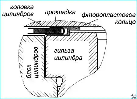
The joint of the cylinder head, block and liner (Fig. 8) is sealed with a gasket made of a sandwich material with edging of the cylinder holes and holes for the passage of coolant.
Split fluoroplastic sealing rings are inserted into the edging of the cylinder holes.
Fastening to the block is carried out by 16 studs with washers and nuts.
Lapping in the valves
Before disassembling the cylinder heads, clean them from oil and carbon deposits and mark the serial numbers of the valves on their plates so that they can be installed in their places during assembly.
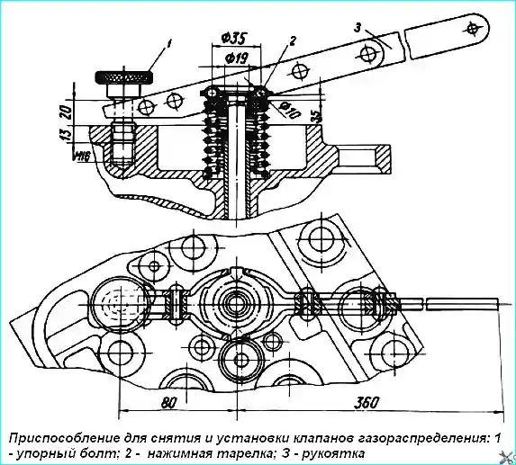
To de-press the valves, it is necessary to install the cylinder head without injectors, rocker arms, rocker arm axles and rocker arm axle mounting studs with the mating surface on the plate so as to provide a stop for the valves.
De-press the valves using the device shown in Fig. 9
For this purpose, screw the stop bolt 1 of the device into the hole for the axle mounting stud rocker arms, pressure plate 2 of the device is installed on the plate of the springs of the corresponding valve and, pressing the handle 3 of the lever of the device, press the valve springs, take out the crackers and remove all the parts of the valve unit.
In the same way, sequentially de-crack all the other valves and remove the valve springs and the parts associated with them.
Turn the cylinder head and remove the valves from the guide bushings.
Thoroughly clean the valves and seats from dirt, carbon deposits and oil deposits, wash in kerosene or a special cleaning solution, dry and inspect to determine the degree of repair.
It is possible to restore the tightness of the valve by lapping only in the presence of minor wear and small cavities on the working chamfer and only if the plate and rod are not warped and there are no local burnouts on the chamfers of the valve and seats.
If such defects are present, lapping should be preceded by grinding the seats and valves or replacing the faulty parts.
For lapping the valves, use a special lapping paste prepared by thoroughly mixing three parts (by volume) of green silicon carbide micropowder with two parts of motor oil and one part of diesel fuel.
Before use, mix the lapping mixture thoroughly, since in the absence of mechanical mixing the micropowder can settle.
Install screw the cylinder head onto a plate or special device with the mating surface facing up.
Apply a thin, even layer of lapping paste to the valve chamfer, lubricate the valve stem with clean engine oil and install it in the cylinder head.
Perform lapping by reciprocating and rotating movements of the valves using a special device or a drill with a suction cup.
Pressing the valve with a force of 20-30 N (2-3 kgf), turn it ⅓ of a turn in one direction, then, loosening the force, ¼ of a turn in the opposite direction. Do not perform grinding in a circular motion.
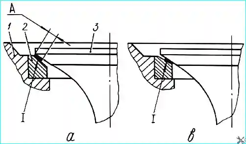
Periodically lifting the valve and adding paste to the chamfer, continue lapping as described above until a continuous matte belt of width "A" of at least 1.5 mm appears on the valve and seat chamfers (Fig. 10).
Breaks in the matte belt and the presence of transverse scratches on it are not allowed.
With correct lapping, the matte belt "A" on the valve chamfer and seat should begin at the larger base of the cone, as shown in Figure 10.
After lapping, thoroughly wash the valves and cylinder head with kerosene or a special cleaning solution and dry.
Install the valves, springs and their fastening parts on the cylinder head and dry the valves using the device shown in Fig. 9.
Check the quality of the lapping for leaks between the valve and the seat by pouring kerosene or diesel fuel, pouring it alternately into the inlet and outlet ports. Well-lapped valves should not allow kerosene or diesel fuel to pass through for one minute.
It is permissible to check the quality of the lapping with a pencil; to do this, apply 10-15 lines at equal intervals across the chamfer of the lapped clean valve with a soft graphite pencil, then carefully insert the valve into the seat and, pressing hard against the seat, turn it ¼ turn.
If the quality of the lapping is good, all the lines on the working chamfer of the valve should be erased. If the results of the quality check of the lapping are unsatisfactory, it must be continued.
The main defects of the cylinder head are:
- - cracks, wear, scratches and cavities on the seats of the exhaust and intake valves, a violation of the seal of the injector cup;
- - wear of the holes in the valve guide bushings, loosening of the fit of the guide bushings in the cylinder head;
- - cracks on the surface of the head mating to the cylinder block and warping of this surface, as well as bending and loosening of the fit of the studs on the cylinder head or damage to the threads on the studs.
The cylinder head is replaced if there are cracks passing through the holes for the valve guide bushings, holes for the injector cups and the seats for the valve seats, and cracks on the walls of the cooling jacket in places inaccessible to repair.
The presence of cracks is determined by visual inspection, as well as by testing the cylinder heads for leaks with water under a pressure of 0.4 MPa (4 kgf/cm2).
The tightness of the cylinder head cooling jacket can be checked by supplying compressed air to it and immersing the head in a bath of water.
Cracks will be visible by the escaping air bubbles.
Cracks and holes in the cylinder head are not allowed, only small cracks on the mating surface between the holes for the injector sprayer and valves are allowed, not affecting the working chamfer of the inlet valve and not violating the tightness.
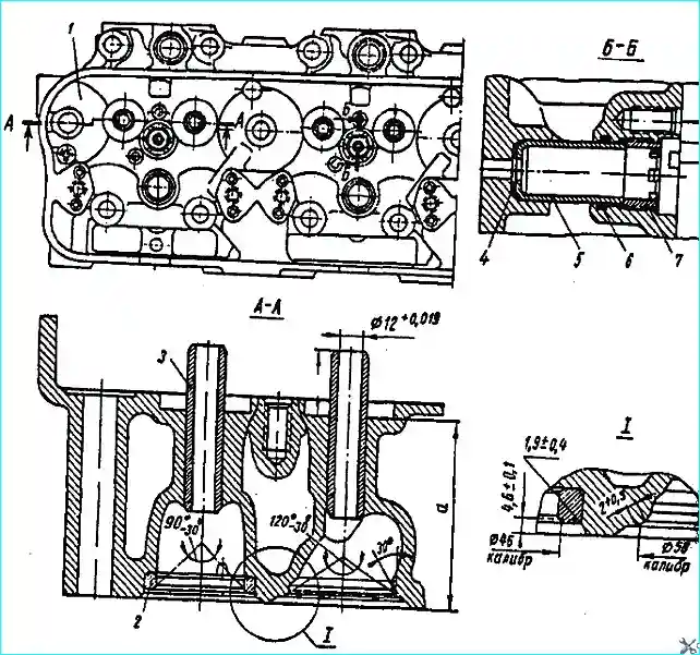
If, when testing the cylinder head for leaks, a leak in the injector cup seal is detected, the cup mounting nut should be tightened. If the leak is not eliminated, remove the cup and replace the sealing ring and washer, and if necessary, the cup.
To install the cup, place washer 4 on the bottom of the socket under the nozzle cup (Fig. 11),
install the sealing rubber ring 6 in the socket, having previously lubricated it with grease, insert the nozzle cup 5 with a reference until it stops and screw in the nut 7 of the nozzle cup with the head (Fig. 12), tightening the nut with a torque of 90-110 Nm (9-11 kgf.m).
Then repeat the tests of the nozzle cup seal for leaks.
Cylinder heads are allowed to be assembled without repair if:
- - the non-flatness of the surface adjacent to the block is no more than 0.1 mm over the entire length and no more than 0.05 over a length of 100 mm;
- - if the width of the working chamfer of the inlet valve seat is 2.0-2.8 mm, the outlet - 1.5-2.3 mm;
- - the recession of the inlet valve relative to the lower plane of the cylinder head is no more than 2.2 mm, and the outlet - no more than 2.7 mm;
- - if the diameter of the inner surfaces of the valve guide bushings is no more than 12.060 mm and if there are no more than two stripped threads in the thread for the studs.
Non-flatness of the surface adjacent to the block is corrected by grinding, ensuring the required non-flatness and the height of the head to the annular rib of at least 131.5 mm; nominal size - 132-0.26 mm.
If the threads in the cylinder head holes are worn or stripped, threads of a repair size are cut or inserts are installed.
Threads are cut in the cylinder head for repair studs of the following sizes: water distribution pipe - M10 x 1.5T to a depth of 14 mm; intake and outlet pipelines - M12 x 1.75T to a depth of 15 mm; injector brackets — M14x2T to a depth of 22 mm.
When repairing threaded holes by installing inserts, drill out the hole with a defective thread and cut a thread for the insert.
Then lubricate the insert with red lead or liquid glass and screw it into the threaded hole until it stops, file the end flush with the plane of the head, punch the insert at three points and calibrate the threaded hole of the insert.
The hole for the injector mounting stud cannot be restored.
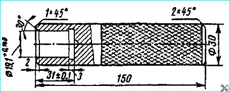
If the inner diameter of the valve guide bushings is worn by more than 12.06 mm, they are replaced with new ones.
Using a mandrel (Fig. 13), the valve guide bushings are pressed into the cylinder head hole and processed with a reamer to the nominal 12+0.019 mm or repair 11.6+0.019 mm dimensions.
The valve guide bushings are pressed in with an interference fit of 0.03-0.05 mm. They should protrude above the valve spring support surface by (31±0.5).
Before pressing in, the guide bushings are soaked in oil for three hours, and the head is heated to a temperature of 160— 170°С.
If the wear of the cylinder head hole under the guide bushing exceeds 19.03 mm, a repair guide bushing is installed. To do this, the hole is reamed to a diameter of 19.2+0.023 mm and the repair bushing is pressed in.
Valve seats are restored depending on the nature of the defect. The working chamfers of the valve seats are processed only after the holes in the valve guide bushings have been restored.
Scratches on the working surface of the intake and exhaust valve seats, wear and dents are eliminated by countersinking or grinding the seat chamfer, while ensuring the minimum necessary metal removal until a clean seat chamfer surface is obtained.
The maximum recession of the new valve plate from the head plane with restored head seat chamfers is allowed: 2.5 mm for the intake valve and 3.0 mm for the exhaust.
The cutting tool for restoring the chamfer must be oriented along the inner diameter of the valve guide to ensure the coaxiality of the chamfer and the inner diameter of the valve guide within 0.025 mm (runout 0.05 mm).

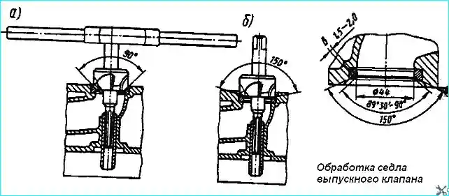
Machining the inlet valve seat chamfer is done in the following order:
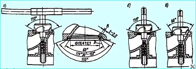
- - mill the working chamfer with a countersink at an angle of 120° (Fig. 14, a) until a clean, flat surface is obtained;
- - mill the lower edge of the working chamfer with a countersink at an angle of 150° (Fig. 14, b), maintaining the required chamfer width within the diameter of 59.4+0.7 mm;
- - mill the upper edge of the chamfer with a countersink at an angle of 60° (Fig. 14, c) until a chamfer width of 2.0-2.5 mm is obtained.
Process the inlet valve seat chamfer in the following order:
- - mill the working chamfer with a countersink at an angle of 90° (Fig. 15, a) until the required cleanliness is obtained;
- - mill the lower edge of the chamfer with a countersink at an angle of 150° (Fig. 15, b) to ensure the size of the working chamfer is within 1.5-2.0 mm.
Scratches and minor wear on the valve seats are eliminated by grinding the seats followed by lapping the valves.
If it is impossible to obtain a working chamfer width on the exhaust valve seat equal to 1.55 - 2.0 mm and an intake valve seat equal to 2.0 - 2.5 mm, as well as in the presence of burnout, cracks, cavities and other defects that cannot be eliminated by processing, the seats are replaced.
The repair seat of the intake valve is made of cast iron, the chemical composition of which is close to the composition of the cast iron of the head cylinders, and the exhaust valve is made of special cast iron. The hardness of the casting is HRC 50-60.
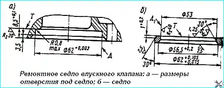
The slot for the repair seat in the cylinder head is bored on a radial drilling machine. The processing of the head for the inlet valve repair seat, the seat dimensions and the processing of the seat chamfer in assembly with the head are shown in Fig. 16.
After boring, the runout of the surface "D" relative to the hole for the valve bushing should be no more than 0.1 mm, the non-perpendicularity of the end face "T" to the surface "D" should not exceed 0.03 mm at the extreme points.
When pressing in a new seat, the cylinder head is heated in boiling water to 90 ° C and kept at this temperature for at least 3 minutes.
Press in the seat with light hammer blows through a copper or brass spacer, ensuring an interference of at least 0.02 mm.
The fit of the seat to the cylinder head is checked with a feeler gauge. A feeler gauge with a thickness of 0.05 mm should not pass.
After pressing in, the valve seats are processed using the technology described above, which ensures the required geometric dimensions of the working chamfer of the valves.
The valves of the engine cylinder head are made of various materials.
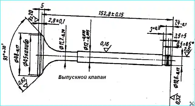
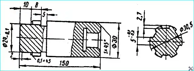
The end of the exhaust valve stem (Fig. 17) is made of 40ХН steel, and the head with the stem are made of 4Х14Н14В2М steel. The valve is hardened and tempered to a head hardness of HRC25-З0 and a stem end hardness of HRC 50-57.
The inlet valve is made of 4Х10СМ2 steel and heat-treated to a hardness of HRC З5-40, and the end to a hardness of HRC 50-57, to a depth of 2-3 mm.
The main defects of the valves are wear or burnout of the working chamfer, bending or wear of the stem along the diameter, as well as wear of the end of the valve stem.
To eliminate wear or burnout of the working chamfer, it is ground cleanly to a roughness of 0.63 μm. In this case, the height of the cylindrical part of the head must be at least 0.5 mm, and if the height is less than 0.5 mm, the valve is rejected.
The chamfer of the exhaust valve is ground at an angle of 45 °, and the intake valve at an angle of 60 °.
The reground working chamfer of the exhaust valve must have the following parameters:
- - thickness of the cylindrical surface belt of the plate is not less than 1.0 mm, angle 91-92°, surface roughness 0.63 μm;
- - runout of the working surface of the chamfer relative to the rod is not more than 0.03 mm, and accordingly for the intake: thickness of the cylindrical surface belt of the plate is not less than 0.75 mm, angle 121-122°, surface roughness is not lower than 1.25 μm;
- - runout of the working chamfer relative to the rod is not more than 0.03 mm.
Usually, before grinding the valve, its stem is checked for bending and, if necessary, straightened.
To check for bending, the valve stem is placed on the indicator prisms and the non-linearity of the valve stem generatrix is checked, which should be no more than 0.01 mm, and the runout of the working chamfer relative to the generatrix should be no more than 0.03 mm.
Straightening is carried out with light blows of a wooden or lead hammer.
When the valve stems are worn, they are ground to a repair size to the following diameters: for the intake - 11.8-0.030 mm or 11.6-0.030 and for the exhaust - 11.8-0.095 mm or 11.6-0.070 mm.
When grinding on a centerless spline machine using the plunge method, it is necessary to subsequently deepen the annular groove for the crackers to a diameter of 10.1-0.12 mm.
When grinding on a cylindrical grinding machine, the valve is inserted end-on into a mandrel with a cylindrical hole and pressed with the center from the side of the valve head.
Definition The tool with a conical surface is fixed in the machine spindle. After grinding, the stem is polished to a roughness of 0.16 µm.
The ovality and taper of the stem generating surface are allowed to be no more than 0.01 mm.
Worn valve stems are restored by tinning followed by grinding to the nominal diameter: Exhaust valve - 12-0.070 mm and inlet - 12-0.030.
Valve stems with a wear in diameter of less than 11.45 mm are rejected.
The worn end of the valve stem is ground and polished to a roughness of 0.32 µm, followed by chamfering 0.45 x 45°
If the distance from the annular groove to the end of the valve stem is less than 7.2 mm, the end is welded with a T-590 electrode or a U8 high-carbon wire.
Then the end is ground, hardened to a hardness of HRC 50-57 and polished. In this case, it is necessary to maintain a size of 7.4-0.1 mm and ensure the perpendicularity of the end relative to the generatrix of the valve stem; a deviation of no more than 0.1 mm over a length of 100 mm is allowed (see Fig. 17).
The valve springs are made of 50KhFA steel. Springs usually have the following defects: loss of elasticity, broken coils and cracks.
If there are broken coils or cracks, the springs are rejected.
Before installing the springs on the engine, they are tested for elasticity on a hydraulic device that allows determining the length of the spring depending on the load.
The outer spring is considered suitable for installation if the length in the free state is at least 74 mm, and at a load of 23.5 - 26.5 kgf at least 56 mm.
The inner spring in the free state is 63 mm, and should have a length of 50 mm at a load of 12.5 - 13.5 kgf.
The valve rocker (Fig. 19) is made of steel 45, and the bushing is made of bronze Br. OCS 4-4-2.5.
The surface of the rocker arm nose is hardened to a depth of 2-5 mm with a hardness of HRC 56 – 63.
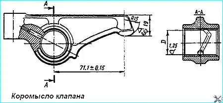
The main defects of the rocker arm are: wear of the hole in the bushing for the rocker arm axis, loosening of the bushing fit in the rocker arm and wear of the nose surface.
The rocker arm is replaced if a crack or break is detected.
If the hole for the rocker arm axis is worn to a diameter of 25.15 mm, only the bushing is replaced. In addition, the bushing is replaced if its fit in the rocker arm is loose.
The fit is checked by light blows with a copper punch.
Before installing a new bushing, check the diameter of the rocker arm hub hole, which should not be more than 27.028 mm. The new bushing is pressed into the rocker arm with an interference fit of at least 0.7 mm.
When installing a new bushing, it is necessary to ensure that the holes in the bushing and the rocker arm coincide, and the joint of the bushing should be at the top of the hole.
The oil groove in the bushing should pass through the aligned hole, while the edges of the groove should not extend beyond the hole. The pressed-in new bushing should be recessed into the rocker arm body by 1 mm on both sides.
The pressed-in bushing is processed with a reamer to a diameter of 25+0.030 mm.
The wear of the rocker arm nose surface is checked with a feeler gauge using a template with a radius of the generating sphere of 15-0.1 mm. A 0.2 mm thick feeler gauge should not pass between the generatrix surface of the nose and the template.
The specified defect is eliminated by grinding to a size (see Fig. 19) of at least 19 mm, ensuring a radius of 15 mm and a roughness of 0.63 µm, which is obtained by polishing with GOI pastes.
Grind manually on a rough grinding machine with a grinding wheel, which must be dressed with a radius of 15 mm.
If grinding the rocker arm nose does not allow removing traces of wear without violating the size of 19 mm, then the surface is welded with a T-590 electrode, which provides a hardness of HRC 50, further processing of the nose surface is similar to that described above.
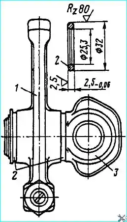
Some engines are equipped with rocker arms with a reduced hub width with 34.9-0.14 mm to 30-0.14 mm, respectively, the length of the rocker arm bushing is changed from — 0.34-0.34 mm to 29-0.28 mm.
Therefore, when installing a new rocker arm 1 (Fig. 19) on an axle 3 of the old design, it is necessary to install one spacer ring 2 on both sides of the rocker arm hub, made of any steel according to the dimensions shown in the figure.
When installing an old rocker arm on an axle of a new design, it is necessary to trim its hub evenly on each side by 2.5 mm; the ends of the rocker arm hub must be perpendicular to the axis of the inner diameter of the bushing with an accuracy of 0.1 mm on a diameter of 30 mm.
A new bushing ku can be pressed in and machined together with the old rocker arm, if the specified requirements are met; when using the old bushing with the new rocker arm, it should be pressed in and trimmed on both sides.


