Maintenance and repair of the YaMZ-238A MAZ gearbox
Caring for the gearbox involves checking the oil level and changing it in the crankcase. The oil level in the crankcase must match the inspection hole
The oil must be drained hot through all drain holes.
After draining the oil, you need to remove the cover at the bottom of the crankcase, which houses the oil pump oil receiver with a magnet, rinse them thoroughly and reinstall them.
In this case, you should pay attention not to block the oil line with the cap or its gasket.
To flush the gearbox, it is recommended to use 2.5 - 3 liters of industrial oil I-12A or I-20A in accordance with GOST 20799-75.
When the gearbox control lever is in the neutral position, start the engine for 7 - 8 minutes, then stop it, drain the flushing oil and fill the gearbox with the oil provided in the lubrication card.
It is unacceptable to flush the gearbox with kerosene or diesel fuel.
During operation of the gearbox drive, adjustments are possible:
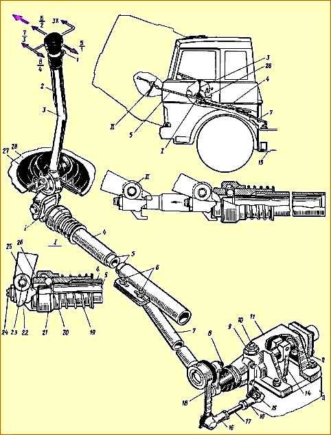
- - position of lever 3 (see Fig. 1) gear shift in the longitudinal direction;
- - position of the gear shift lever in the transverse direction;
- - locking device for telescopic elements of longitudinal thrust.
To adjust the angle of inclination of the lever 3 in the longitudinal direction, it is necessary to loosen the nuts of the bolts 6 and by moving the rod 4 in the axial direction, set the angle of inclination of the lever to approximately 85 ° (see Fig. 1) in a neutral position in the gearbox.
Adjustment of the position of the lever in the transverse direction is carried out by changing the length of the transverse rod 17, for which it is necessary to disconnect one of the tips 16 and, by unscrewing the nuts, adjust the length of the rod so that the gearbox control lever is in the neutral position against engaging 6 - 2 and 5 - 1 gears, had an angle of approximately 90˚ to the horizontal plane of the cabin (in the transverse plane of the car).
Adjustment of the gear shift drive locking device must be done as follows:
- - raise the cabin;
- - unpin pin 23 and disconnect rod 4 from fork 22;
- - clean the earring 25 and the internal rod from old grease and dirt;
- - push in the internal rod until the locking sleeve 15 “clicks”;
- - loosen the nut of the earring 25 and, inserting a screwdriver into the slot of the shank of the internal rod, unscrew it until the angular play of the earring disappears;
- - holding shank 24 from turning, tighten the lock nut;
- - check the quality of the adjustment. When the locking sleeve 21 is shifted towards the spring 19, the internal rod should be pulled out to its full length without jamming, and when the rod is pushed inward until it stops in the grooves, the locking sleeve should move clearly with a “click” until the sleeve stops in the lower protrusion of the earring.
When adjusting the drive, the following requirements must be observed:
- - make adjustments with the cab raised and the engine not running;
- - avoid bending and bending of the outer and inner movable rods;
- - to avoid breakage, connect rod 4 to fork 22 so that the hole in the shackle for finger 23 is located above the longitudinal axis of rod 4;
- - check the neutral position of the gearbox with the cab raised by freely moving the lever 18 of the gear shift mechanism in the transverse direction (relative to the longitudinal axis of the car).
Roller 12, when the box is in the neutral position, has an axial movement of 30 - 35 mm, and the compression of the spring is felt.
The gearbox drive adjustments described above should be made when removing and installing the engine and cab.
Possible gearbox malfunctions
Reasons
Remedy
It is difficult to engage gears in the main gearbox. Shifting into first gear and reverse occurs with a grinding noise
- Incomplete disengagement of the clutch (the clutch is moving)
Adjust the free play of the clutch pedal or replace damaged parts
It is difficult to engage second, third, fourth and fifth gears. Switching on occurs with a grinding sound om
- Wear of synchronizer cone rings
Replace synchronizer
Gears do not engage in the main box
- Wear of the gear rims of the synchronizer carriage, gear couplings mounted on the gears of the 2nd, 3rd, 4th and 5th gears, the gear rims of the first gear and reverse gears, or the gear rims of the first gear and reverse gears
Replace faulty parts
- Worn parts or misadjustment of the remote gear shift drive
Replace faulty parts; adjust the remote gear shift actuator
Shifting gears in the range-shifter occurs with a bang and a grinding noise
- Increased pressure in the pneumatic system for controlling the range-multiplier
Adjust the pressure relief valve
- - Wear of cone rings in the synchronizer
- - Wear of the locking chamfers of the fingers and the synchronizer carriage
Replace synchronizer
Failure to switch off or slow engagement of gears in the range-shifter when the main gearbox shift lever is in neutral position.
The indicator lamp does not go out for a long time when the fast range is turned on and does not light up for a long time when the slow range is turned on.
Air exits through the air distributor saloon
- Intake valve rubber wear
Replace valve
- Worn valve stem sealing ring
Replace the O-ring
- Uneven fit of the intake valve to the body shoulder
Replace the O-ring
- Intake valve stuck in the depressed position
Replace faulty parts
- Hardening of the O-ring ring of the intake valve body
Wash, blow out and lubricate the valve stems and the cover hole. If necessary, polish the stem
- Wear or hardening of the power cylinder piston rod o-rings
Replace the O-rings
- Air comes out through the gearbox breather when the slow gear is engaged in the range
Replace the O-ring
- Wear or hardening of the air distributor piston O-ring
Replace the O-rings
- Wear or hardening of the air distributor spool o-rings
Replace the cuff
- Low pressure in the gearbox pneumatic system
Replace the cuff
- Wear or hardening of the power cylinder piston cuff
Replace the diaphragm
- Rupture of the air distributor inlet valve diaphragm
Replace the diaphragm
- Air exits through the gearbox breather.
Clean or replace the breather
- Rupture of the diaphragm of the first gear and reverse locking device
Replace faulty parts
- Air comes out through the gearbox breather when fast gear is engaged in the range
Clean or replace the breather
Self-switching of gears while the vehicle is moving
- Incomplete gear engagement due to wear of the fork cotters, due to misadjustment of the remote control drive
Tighten fastenings, replace worn parts, adjust control drive.
- Wear of gear couplings and synchronizer carriages due to incomplete engagement
Replace worn parts
Increased noise during gearbox operation
- Loosening the bolts securing the clutch housing to the flywheel housing
Tighten the bolts
- Wear of gear teeth
Replace gears
- Wear of shaft or gear bearings
Replace bearings
- Not enough oil in the gearbox
Add oil to the upper mark on the oil level indicator
Oil leak from the gearbox
- Worn or lost elastic cuffs
Replace cuffs
- Increased pressure in the crankcase
Rinse the breather
- Violation of tightness along sealing surfaces
Tighten fasteners
Enabling the slow range at vehicle speeds exceeding the recommended
- Opening the electrical circuit contacts
Restore contact
- Broken wires of the ASBP system
Replace wire
- ASBP blocking relay is faulty
Replace relay 6312.3747
- Speed sensor is faulty
Replace speed sensor 1101.3843
- Blocking valve is faulty
Replace faulty parts
Gearbox repair
Removingthe gearbox.
To remove it you need:
- - tilt the cabin;
- - drain the oil from the gearbox;
- - remove the landing gear platform;
- - loosen the clamps, remove the clean air pipe of the air cleaning system;
- - unscrew, unscrew the nut and disconnect the gearbox control rod from the gearshift lever;
- - unscrew the bolts and remove the second frame cross member;
- - disconnect the exhaust pipe of the muffler;
- - unscrew, unscrew the nuts and remove the rear engine mount;
- - unscrew the bolts securing the bracket with the fuel pipes from the gearbox cover;
- - unscrew the bolts and remove the rear engine mount brackets;
- - disconnect the clutch release shaft lever from the valve stem fork;
- - disconnect the electrical wires from the gear shift warning light sensor in the additional box;
- - unscrew the bolts securing the propeller shaft to the gearbox flange, disconnect the propeller shaft and hang it on the left frame side member;
- - disconnect the air supply line to the pressure reducing valve;
- - unscrew the bolts and remove the muffler pipe;
- - place a ditch lift with a device for removing and installing the gearbox or another lifting vehicle under the gearbox;
- - unscrew the bolts securing the clutch housing from the flywheel housing, remove the gearbox and disconnect it from the engine;
- - lower the gearbox on the lift, lift the rear of the car and roll out the lift with the gearbox from under the car, then lower the car.
The gearbox is installed in the reverse order.
Disassembling the gearbox
The gearbox should be disassembled in the following sequence:
- - disconnect the air ducts from the air distributor;
- - remove the top cover of the additional box with the control mechanism assembly;
- - undo the cotter pins and unscrew the three locking bolts on the holder of the small synchronizer of the additional box;
- - remove the small synchronizer from the secondary shaft of the main box;
- - unscrew the nuts securing the additional gearbox housing to the main gearbox housing;
- - disconnect the additional gearbox from the main gearbox;
- - remove the propeller shaft mounting flange, the output shaft cover, the speedometer drive worm, the rear support ball bearing, the front support roller bearing, the synchronizer carriage and remove the shaft together with the rear support roller bearing.
Further disassembly of the additional gearbox is not difficult. The shafts from the box housing must be removed as an assembly.
To disassemble the main gearbox, you must first remove the secondary shaft bearing retaining ring, then use puller bolts to remove the secondary shaft bearing centering ring.
The shafts from the main gearbox housing must be removed as an assembly. After disassembling the box assembly, the parts must be washed in kerosene or diesel fuel and blown with compressed air.
External inspection reveals cracks, breaks, thread breaks, chipping and broken gear teeth, and other defects. Gears must be replaced if there are cracks or broken teeth, as well as increased wear of the teeth.
The fastest-wearing gearbox component is the synchronizer, which may have defects such as loose fitting of the clutch pins on the carriage, wear of cone rings, carriage teeth and spline holes.
When the coupling on the synchronizer carriage is loosened, the unusable pins are drilled out and replaced with new ones welded with brass. The welding site is cleaned.
After replacing failed parts, assemble the gearbox in the reverse order.
When installing the gearbox on a vehicle, it is recommended to use lifts or special stands to avoid breaking or bending the driven clutch discs. After installing the gearbox, its drive is adjusted.
")

")
")
")
")
")
")
")