Before assembly:
- - carefully clean and check all details;
- - it is recommended to unpack a new bearing immediately before installation, do not remove the conservation grease from new bearings;
- - it is forbidden to reuse retaining rings and seals removed during disassembly;
- - with a tight fit of parts, do not use a copper or brass hammer;
- - all parts intended for pressing must be pre-lubricated;
- - it is recommended to use a specially adapted mandrel each time to prevent metal particles from entering the crankcases and bearings;
- - some o-rings must be filled with grease inside the rims;
- - hot-mounted parts are heated by a jet of hot air in a heat chamber.
Before starting assembly, thoroughly clean all surfaces of the parts to which sealants will be applied. The remains of the old tool must be removed. Threaded connections are cleaned with a brush, if necessary, cut with a tap.
Assembly order
- 1. Install the engine crankshaft (See the article "Installing the YaMZ-650 crankshaft")
- 2. Install the connecting rod and piston group (See the article “Repair of the YaMZ-650 connecting rod and piston group”)
- 3. Set End Sheet:
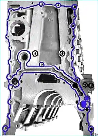
- Apply Loctite 518 sealant to the end of the cylinder block for the installation of the end sheet, as shown in Fig. 1.
- Install two rails in the cylinder block.
- Install the end sheet in place and screw the bolts of its fastening to the cylinder block.
- 4. Install intermediate gear axles.
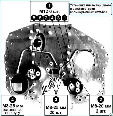
Tighten the bolts for fastening the end plate with a torque of Mcr = 20 ± 4 Nm, and the bolts for fastening the gear axles with an intermediate torque of Mcr = 90 ± 18 Nm according to the order in Fig. 2.
4. Install flywheel housing:
- Install the pilot pin in the cylinder block.
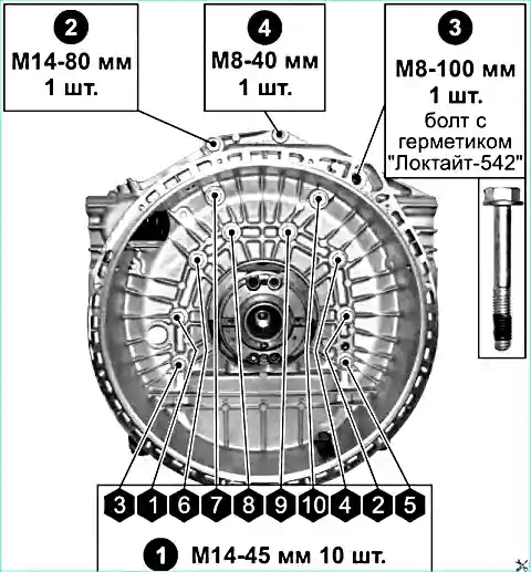
- Apply sealant to the end of the block for installing the flywheel housing (see Fig. 3).
- Install the flywheel housing on the block and tighten the bolts of its fastening.
- Tighten crankcase bolts to torque:
- - for M14 bolts - Mcr = 150 ± 30 Nm;
- - for M8 bolts - Mkr = 20 ± 4 Nm. Apply Loctite 542 sealant
- to the threaded part of the M8x1.25 -100 mm bolt
5. Install the flywheel housing seals (see Fig. 4):
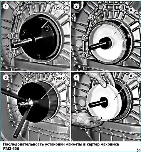
- Install tool 2562 and protective ring (A) on it.
- Install the crankshaft seal after lubricating the outer surface (Michelin-Tigre80 or Pneufix Grease).
- Remove the protective ring (A).
- Remove fixture 2562.
The cuff is supplied on a protective ring that is placed on the mounting tool.
The seal must remain on this ring until it is finally installed in the crankcase.
Do not grease the rims. It is forbidden to use the cuff removed from the ring.
- 6. Install the flywheel (see the article "Removing and installing the YaMZ-650 flywheel").
- 7. Set block stiffener:
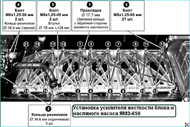
- Install rubber rings (2) and a gasket (1) on the stiffener of the block (see Fig. 5).
- Install the stiffener on the cylinder block.
- Insert the block stiffener mounting bolts and tighten Mcr = 30 ± 6 Nm, observing the tightening order (see Fig. 5).
- 8. Install oil pump:
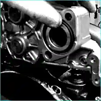
- Install the oil pump with guide bushings in the holes of the end sheet, ensuring that it is engaged pump intermediate gear with crankshaft gear.
- Turn on the oil pump mounting bolts and tighten crosswise Mcr = 20 ± 4 Nm.
- Install the rubber ring in the oil pump (see Fig. 6).
- Install the oil intake pipe.
- Tighten the bolts (4) (see Fig. 5) of the oil intake pipe Mcr = 20 ± 4 Nm.
- Pick up the oil supply pipe with the ring and install it.
- Install the sleeve and tighten the bolt (5) (see Fig. 5).
- 9. Install intermediate gears:
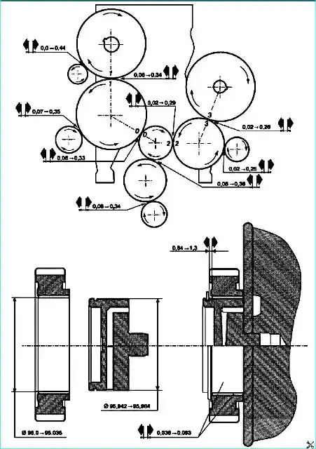
Lubricate the ring gear and seating surface with oil and install the intermediate gears of the camshaft and fuel pump according to the marks (0-0, 2-2) (see Fig. 7).
Replace the retaining rings.
Check the lateral and interdental gap (see Fig. 7).
- 10. Install the camshaft (See the article “Removing and installing the YaMZ-650 camshaft”).
- 11. Install the fuel pump (See the article "Removing and installing the fuel pump and the YaMZ-650 diesel rail").
- 12. Install front cover:
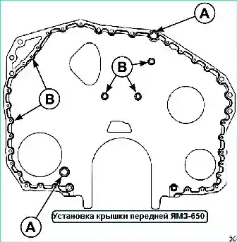
- Apply CAF44 Silicone sealant (B) to the surface of the end sheet under the front cover (see Fig. 8).
- Install guide bushings (A).
- Install the front cover on the end sheet.
- Install the front left and right supports on the front cover.
- Screw the nuts onto the support bolts and tighten with a torque of Mcr = 100 ± 20 Nm.
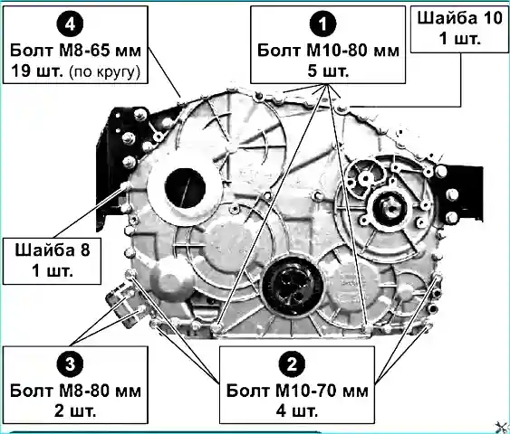
Insert the mounting bolts into the holes in the front cover and tighten in the order shown in Fig. 9 next moment:
- - for M10 bolts Mcr = 50 ± 10 Nm;
- - for M8 bolts Mcr = 27 ± 5.4 Nm.
13. Installing the front cuff on the crankshaft:
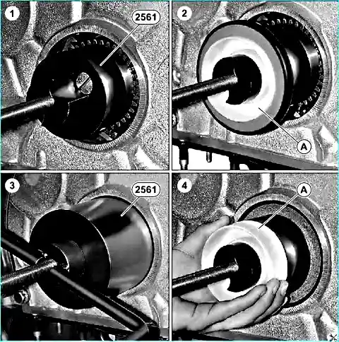
- Install tool 2561 (see Figure 10).
- Install the protective ring (A) on tool 2561, observing the direction.
- Install the front crankshaft seal, having previously lubricated the outer surface (Michelin-Tigre80 or Pneufix grease).
- Remove the protective ring (A).
- Remove fixture 2561.
The cuff is delivered on a protective ring that is placed on the installation tool.
The seal must remain on this ring until it is finally installed in the crankcase. Do not lubricate the edges. It is forbidden to use the cuff removed from the ring.
14. Air compressor installation:
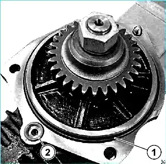
- Install the rubber ring (1) (650.3509075) on the air compressor mounting flange, pre-lubricating it with oil.
- Install the gasket (2) (312384) into the groove on the flange, after lubricating it with oil (see Fig. 11).
- Install the air compressor in the seat on the back side of the 2-stud flange end hole sheet, ensuring that the compressor gear and the drive gear are engaged.
Screw the nuts onto the studs, screw the bolt with the bushing into the end sheet.
Tighten the bolt and 2 nuts to Mcr = 40 ± 8 Nm. First tighten the bolt, then the top and bottom nuts, and then the bolt again.
15. Install oil sump:
- Check the tightness of the studs.
- Install double-sided tape UNV.
- Replace the oil pan gasket.
- Install the oil sump.
- Install prefabricated elastic washers on the studs.
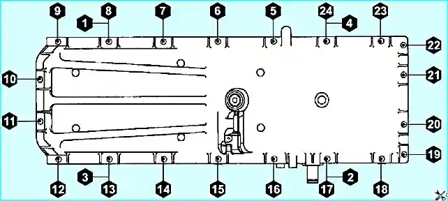
- Tighten the nuts in the order shown in Fig. 12, and tighten with torque Mcr = 20 ± 4 Nm
- 16. Install the oil separator impeller cover:
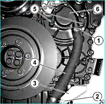
Installing the roof Make the oil separator impeller and exhaust pipes in the reverse order of removal (see Fig. 13).
Tighten the bracket for fastening the exhaust pipe to a torque of Mcr = 50 ± 10 Nm, tighten the clamp bolt to a torque of Mcr = 5 ± 1 Nm, tighten the clamp fastening bolt to a torque of Mcr = 20 ± 4 Nm.
17. Install Pushers:

Lubricate and install the tappets in the cylinder block, aligning the tappet grooves with the grooves of the block holes.
Install the lock pushers of the intake and exhaust valves in the grooves of the plate.
Fix the plate fixing bolts and tighten them with a torque Mcr = 20 ± 4 Nm.
Apply “CAF44 Silicone” sealant (other brands of silicone based sealant may be used) as shown in Fig. 14 in places (A, B).

- Install the side plate so that the manufacturer's mark is in the lower left corner.
- Install the bolts and tighten to the recommended torque in the order shown in Fig. 15.
- Install the cylinder head (See the article "Repair of the YaMZ-650 cylinder head").
- Install engine harnesses (See the article "Removing and installing the ECU unit and YaMZ-650 engine harnesses").
- Install cylinder head cover:
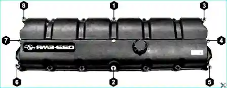
- Install the cylinder head cover assembly with gasket.
- Install 16 bolts in the holes of the cylinder head cover, tighten 8 bolts (see Fig. 16) with a torque of Mcr = 2 Nm in the indicated order.
- Tighten the remaining bolts to the same torque in any order.
- Install the ramp and high pressure pipes (See the article "Removing and installing the fuel pump and rail of the YaMZ-650 diesel engine").
- Install fine fuel filter:
- Install the fuel filter bracket on the left side of the block by screwing in the mounting bolts with washers.
- Tighten the bolts with a torque Mcr = 27 ± 5.4 Nm.
- Install the fine fuel filter on the bracket, screw 3 fastening bolts into the bracket and tighten with torque Mcr = 50 ± 10 Nm.
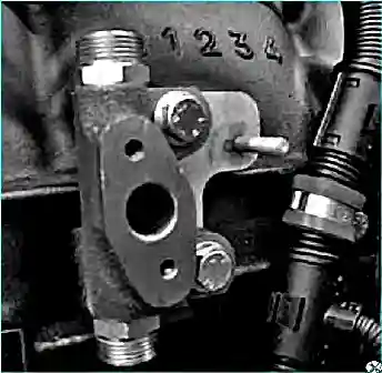
- Install the fuel pressure and temperature sensor housing with the fuel pipe mounting bracket (see Fig. 17).
- Tighten the bolts of its fastening to the moment Mcr = 27 ± 5.4 Nm.
- Install low pressure pipes:
- Install the low pressure pipes in the reverse order of removal. Wrap union nuts of low-pressure pipes with torque Mcr = 28 ± 2 Nm. Tighten the nuts of the brackets for fastening the low-pressure pipes with a torque of Mcr = 15 ± 3 Nm.
- Install a centrifugal oil cleaner (See the article "Removing and maintaining the CMO")
- Install intake manifold:
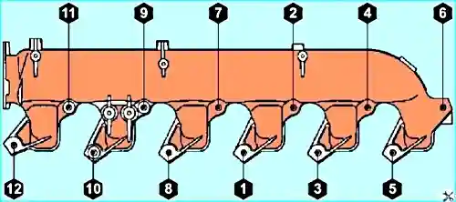
- Install 4 technological guides in the corresponding holes of the cylinder head (11, 7, 2, 6) (see Fig. 18).
- Install the front and rear manifold gaskets onto the cylinder head.
- Install the intake manifold using the guides on the cylinder head.
- Install 8 M10x1.5-80 mm bolts into the manifold mounting holes (9, 4, 10, 8, 1, 3, 5, 12), screw them into the cylinder head and tighten to 20 Nm.
- Retrieve guides.
- Install the M10x1.5-55 mm bolt into the manifold mounting hole (6), screw it into the cylinder head and tighten to 20 Nm.
In the remaining 3 vacated holes (11, 7, 2) screw 3 bolts M10x1.5-80 mm and tighten with a torque of no more than 20 Nm.
Finally tighten all bolts to 60 ± 12 Nm (tighten the bolts in the order shown in Fig. 18).
Next, proceed in the reverse order of removal.
26. Install exhaust manifold:

- Set to holes (1,3,5,7,9,11) (see Fig. 19) mounting the exhaust manifold on the cylinder head 6 technological guides.
- Install 3 exhaust manifold gaskets and exhaust manifold assembly on the rails.
- Install 6 bolts with bushings into the holes of the manifold flanges and screw in two or three threads by hand.
- Remove the technological guides, install 6 bolts with bushings into the vacant holes and screw in two or three threads by hand.
- Pre-tighten the exhaust manifold mounting bolts to 20 ± 4 Nm and finally tighten to 40 ± 8 Nm. Tighten the bolts in order according to Fig. 19
- Install the turbocharger (see the article "Removing and installing the YaMZ-650 turbocharger")
- Install heat shields:
- Install heat shields in the reverse order of removal. Tighten the bolts for fastening the front and rear heat shields to Mcr = 60 ± 12 Nm and the bolts for fastening the middle heat shield to Mcr = 20 ± 4 Nm.
- Install damper on exhaust (fig. 20):
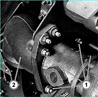
- Install a metal gasket on the turbocharger studs with the convex side out.
- Install the damper on the exhaust to the position of the plug on the cylindrical part in the direction opposite to the cylinder block.
- Install washers on the TKR studs and screw on the damper fastening nuts.
- Tighten the nuts with a torque Mcr = 20 ± 4 Nm.
- Install the damper bracket onto the exhaust manifold studs.
- Install the washers, tighten the nuts of the bracket.
- Install 2 bolts, 2 washers and 2 nuts into the holes of the bracket and damper flange from the side of the bracket.
- Tighten the nuts securing the bracket to the exhaust manifold to a torque of Mcr = 60 ± 12 Nm and the nuts of fastening the damper on the exhaust to the bracket to a torque of Mcr = 60 ± 12 Nm.
- Install the outlet pipe in the reverse order of removal. Tighten the fitting nuts to the recommended torque.
- Install the water pump (See the article "Removing and installing the YaMZ-650 water pump").
- Install the starter (fig. 21):
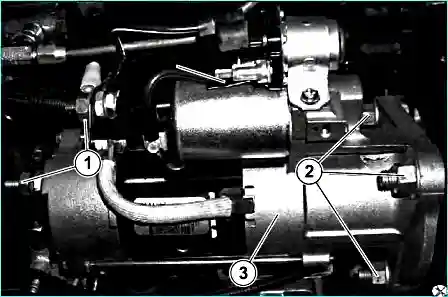
- Install the starter in the order of removal.
- Tighten the starter mounting nuts to the recommended torque
- Install the fan drive (See the article "Removing and installing the YaMZ-650 fan drive").
- Install the damper (See the article "Removing and installing the torsional vibration damper (damper) of the YaMZ-650 diesel engine")
- Install the generator (Fig. 22):
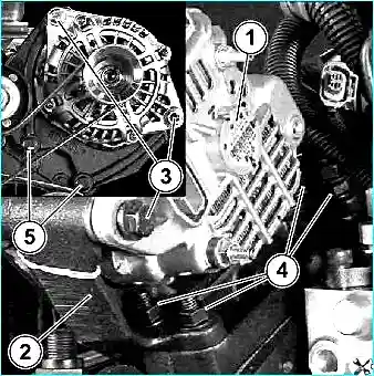
- Install the alternator bracket on the studs, screw the nuts onto the studs and tighten to a torque of Mcr = 60 ± 12 Nm.
- Insert 2 bolts into the holes of the generator bracket, screw them into the front cover and tighten with a torque of Mcr = 20 ± 4 Nm.
- Install the alternator and tighten the nuts to the recommended torque.
- Install the drive belts of the units and tensioners (See the article "Removing and installing drive belts and tensioners YaMZ-650").
- Install the electronic control unit (See the article "Removing and installing the ECU unit and harnesses of the YaMZ-650 engine").
- Install a liquid-oil heat exchanger (See the article "Removing and installing the YaMZ-650 liquid-oil heat exchanger").


