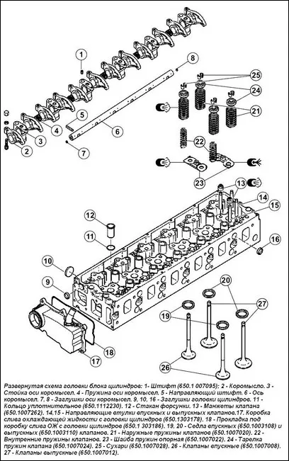
Disassembling the cylinder head (see Fig. 1)
- 1. Unscrew the nuts (311442) securing the fuel supply fittings to the injectors
- 2. Remove the fuel supply nipples to the injectors (650.1112154).
3. Unscrew the bolts (a) (300144) (see Fig. 2) securing the injector brackets.
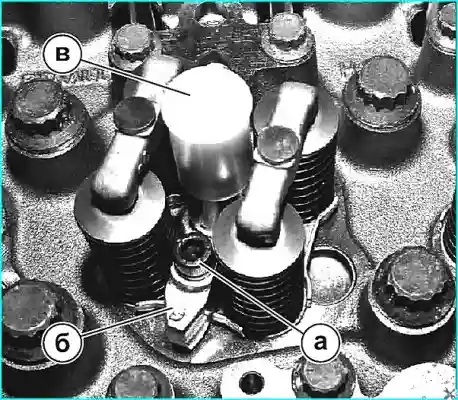
- 4. Remove the injector mounting brackets (6) (650.1112163) (see Fig. 2).
- 5. Remove the injectors (b) (650.1112010) (see Fig. 2).
- 6. Remove copper washers (312383).
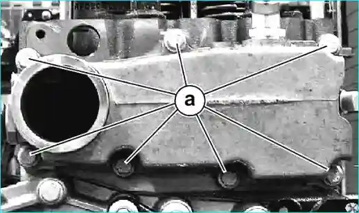
- 7. Unscrew 7 bolts securing the coolant drain box to the cylinder head (a) (310022) (see Fig. 3).
- 8. Remove the coolant drain box from the head (17).
- 9. Remove the gasket (18) of the coolant drain box.
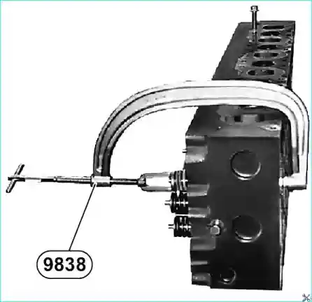
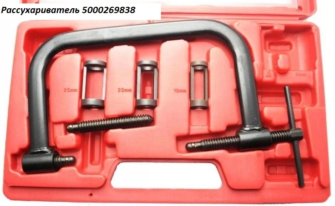
- 10. Compress the springs using tool 9838 (see Fig. 4).
- 11. Remove the crackers (25).
- 12. Remove the plates (24) and springs (21, 22).
- 13. Remove the spring support washers (23).
- 14. Remove the valves (26, 27) and arrange them in order.
- 15. Remove the valve cuffs (13).
- 16. Remove the valve guides (14, 15)
- 17. Weld the washer to the valve seat.
- 18. Push the seats (19, 20) out of the head.
- 19. Cut an internal thread M26x1.5 mm in the injector cups
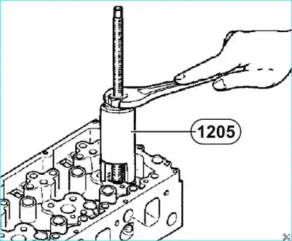
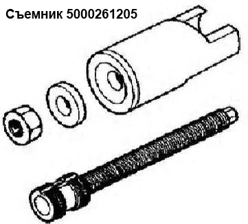
- 20. Remove the injector cups (12) using tool 1205 (see Fig. 5).
- 21. Remove the O-ring (11). The injector cups must be replaced with the cylinder head removed.
Disassembling the rocker arms with the axle and struts. (see Fig. 1)
- 1. Remove the guide sleeve (1).
- 2. Remove the pins (5).
- 3. Remove the rocker arms (2), struts (3) and springs (4).
- 4. If necessary, remove the plugs (7, 8).
Assembling the rocker arms with the axle and struts. (see Fig. 1)
- 1. Install plugs (7, 8) using Loctite 542 sealant.
- 2. Lubricate and install struts (3), rocker arms (2) and springs (4).
- 3. Install pins (1, 5).
Cleaning the cylinder head:
(See Fig. 1) Clean the cylinder head if necessary, remove plugs (9, 10, 16) to remove carbon deposits.
Check the cylinder head and MGR parts. (See Appendix B)
- 1. Check the bearing surface of the cylinder head for the gasket.
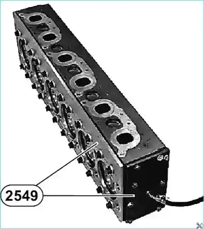
- 2. Check the tightness of the cylinder head before installation.
Attach device 2549 with air pressure of 6 bar, immerse the head in hot water (80˚ C) and make sure there are no bubbles (see Fig. 6).
- 3. Check the spring calibration.
- 4. Check the radial clearance between the valve and the guide.
- 5. Check the valve indentation and protrusion.
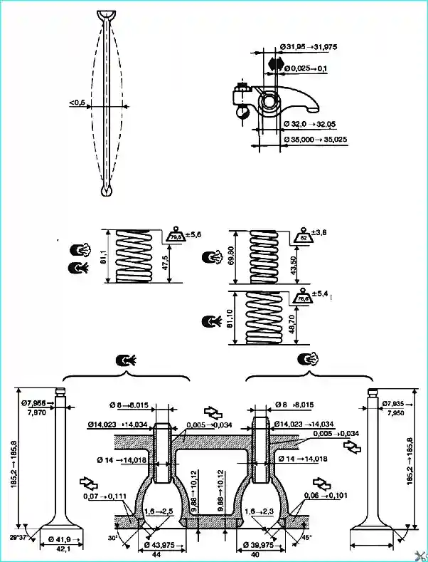
Cylinder head dimensions and tolerances
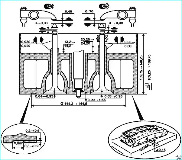
Cylinder head assembly
Installing plugs:
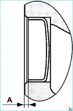
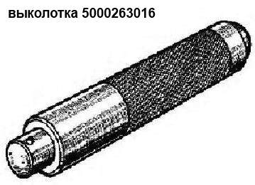
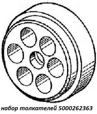
- 1. Install plugs (9, 16) (see Fig. 1) using tools 3016 + 2363 25 mm.
- 2. Install plug (10) (see Fig. 1) using tool 3016 + 2363 42 mm.
- 3. Use sealant “Loctite 542” when installing plugs.
- 4. Check for recess “A” = 1.5 ± 0.5 mm (see Fig. 9)
Installing the injector cup:
- 1. Put the O-ring in place (11) (see Fig. 1).
- 2. Lubricate the injector cup with consistent grease.
- 3. Install the injector cup (12) (see Fig. 1).
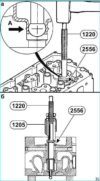
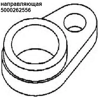
- 4. Install tool 2556.
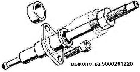
- 5. Flare to “A” (see Fig. 10a) using tool 1220.
- 6. Remove tool 1220 using tool 1205 (see Fig. 10B)
- 7. Remove tool 2556
- 8. Check for leaks.
Installing valve guides:
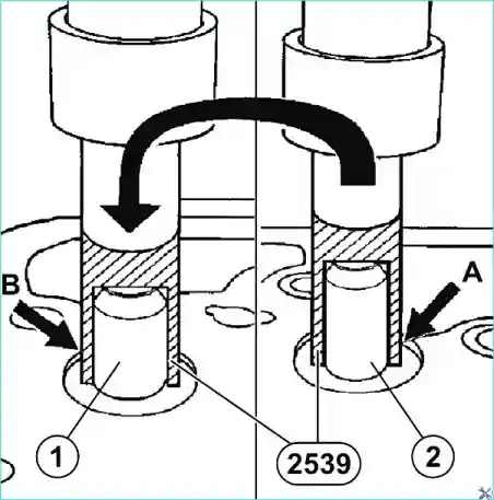
- 1. Lubricate the guides with grease.
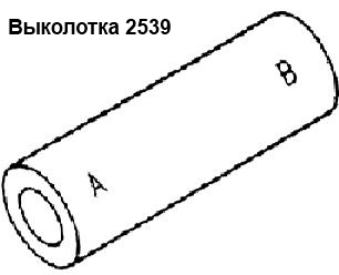
- 2. Press in the inlet (1) and outlet (2) valve guides using tool 2539 and a press (see Fig. 11).
- After replacing the guides, the valve seats are ground in. Perform lapping after installing the seats.
Installing the valve seats:
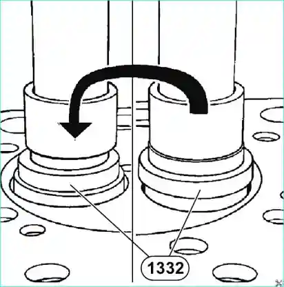
- 1. Cool the valve seats in liquid nitrogen or for about 12 hours in a freezer.
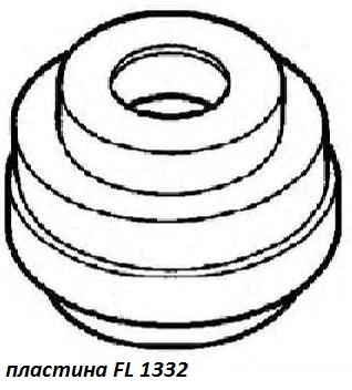
- 2. Install the valve seats using fixture 1332 and a press (see Fig. 12).
Lapping the valve seats:
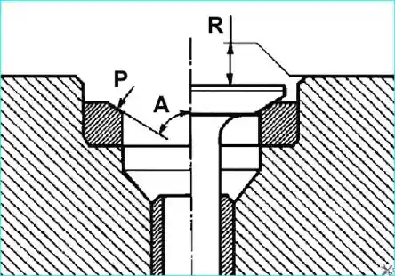
Before grinding the seats, check the condition of the valve guides. Replace if necessary.
Methodology:
- - the valve guides must ensure the centering of the tool.
- - to determine the amount of metal to be removed, take into account the values "R" of the valve recess; process the seating surface "P" using device 9732, observing the angle "A":
- - at the inlet 60˚,
- - at the outlet 45˚
Depending on the equipment/tool used, the angles are specified either in relation to the plane of the joint of the cylinder head with gasket, or in relation to the valve axis.
Installing the valves (see Fig. 1):

Do not grind the valves themselves, no lapping is allowed.
- 1. Place the cuffs (13) on the guide bushings of the exhaust valves.
- 2. Lubricate with oil and install the valves.
- 3. Install the spring support washers (23).
- 4. Install the springs (21, 22) with plates (24).
- 5. Install crackers (25) using device 9838 (see Fig. 14).
Installing injectors:
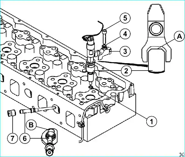
- 1. Install the injector (2) with copper washer (1) (312383) into the injector hole in the cylinder head. (When installing it, the fuel supply hole should be directed towards the inlet ports of the cylinder head).
- 2. Install the fuel supply nipple to the injector (6). (Observe orientation (B)).
- 3. Maneuver the injector (2) and the fuel supply nipple to the injector (6) so that the cones of the nipple and the hole in the injector converge.
- 4. Tighten the nipple mounting nut (7).
- 5. Install the injector mounting bracket (3).
- 6. Install the spherical washer (4) (312391).
- 7. Tighten the injector bracket mounting bolt (5).
- 8. Pre-tighten the bracket bolt injector mounting bolt (5) and fitting mounting nut (7) with a torque of no more than 5 Nm.
- Finally tighten the injector bracket mounting bolt (5) and fitting mounting nut (7) with a torque of 60 Nm.
- 9. Check the injector protrusion.
Installing the coolant drain box from the cylinder head:
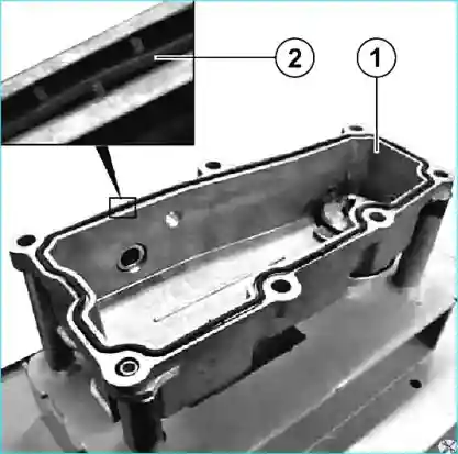
- 1. Install the seal (2) into the coolant drain box from the cylinder head (1) (see Fig. 16).
- 2. Install the coolant drain box from the cylinder head.
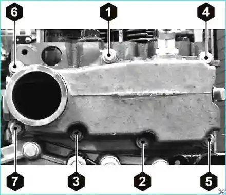
- 3. Tighten the bolts securing the coolant drain box to the cylinder head and tighten them finally to Mkr = 20 ± 4 Nm, observing the specified tightening order (see Fig. 17)
Cylinder head repair tools
