The transverse angle of the king pin of 5˚, as well as the camber angle of the wheels of 1˚, are ensured by the manufacture of parts of the front axle. These angles are not adjustable.
The longitudinal angle of inclination of the kingpin 2˚30’ is ensured by the position of the spring on the frame.
Adjusting the toe of the front wheels, ball joints, steering rods and wheel bearings
Adjusting wheel toe
If the wheels are installed correctly, the car has good stability when driving in a straight line and controllability when cornering.
During operation, wheel alignment angles may change due to wear of parts.
Set the angle of toe-in of the wheels in the horizontal plane by adjusting the length of the transverse steering rod 21 (Fig. 1), the ends of which have right and left threads.
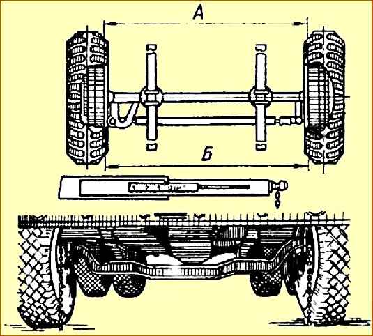
The amount of wheel toe is measured using a special ruler, model 2182, and is determined by the difference in the distances between the ends of the brake drums in the horizontal plane.
Size “B” (back) should be larger than size “A” (front) by 1-2 mm.
To adjust the toe-in of the wheels, loosen the bolts of the terminals of both tie rod ends and by rotating the rod (screwing it into the tip with greater toe-in and unscrewing it with insufficient toe-in), change its length so as to ensure the normal amount of toe-in of the wheels.
After adjustment, carefully tighten the nuts of the tip bolts.
Adjust the angles of rotation of the wheels by changing the position of the thrust bolts that limit the rotation of the wheels.
The thrust bolts are screwed into the steering knuckles.
When the bolt is removed, the angle of rotation of the wheel decreases and vice versa.
Adjusting wheel toe-in of all-wheel drive MAZ vehicles
The difference (B-A) should be 0.5-3.5 mm (Fig. 2).
If necessary, adjust wheel alignment in the following order:
- - set the wheels to the position corresponding to straight movement;
- - loosen the tightening of the tie bolts of both tie rod ends;
- - unscrew the nuts securing the ball pins of the ends in the levers and remove the rod;
- - by unscrewing or screwing in the tips by rotating the rod, set the toe-in of the wheels within the specified limits.
It should be borne in mind that unscrewing the tips by one turn increases the difference in distances by about 5 mm, and screwing them in reduces it by this amount.
If the amount of toe differs from the established norm by no more than 2.5 mm, you can adjust the toe with one of the tips.
Connect the transverse link with the levers and check the amount of toe-in of the wheels and, if it is normal, attach the transverse link to the levers and tighten the tie rod end bolts.
In this case, the vases of both tips must be in the same plane.
The clearance in the steering rod joints is checked by inspecting the connection when turning the steering wheel to the right and left (for longitudinal rod when the engine is not running, for transverse rod when the engine is running).
Adjusting the ball joints of the steering rods
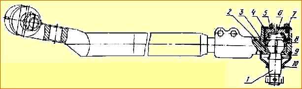
When adjusting the ball joints of the longitudinal steering rod, screw the adjusting plug 5 (Fig. 3) all the way (tightening torque 118-157 Nm), and then unscrew it ⅛ turn.
Place cover 6 in place, turning it 120˚ relative to the original position, and crimp the edge into the groove of tip 3 to lock nut 5.
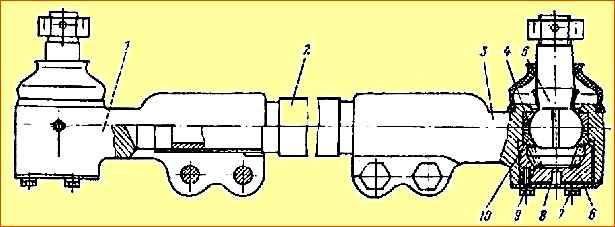
Whenever adjusting the ball joint, turn the cover 6 when installing it to 120˚, having first straightened the deformed section of the cover. The ball joints of the tie rod (Fig. 4) and the power steering cylinder are adjusted in the same way.
Adjusting the front wheel hub bearings
Adjust the front wheel hub bearings in the following order:
- - remove cover 8 and loosen bearing nut 9 by unscrewing bolt 10. When turning the hub, check that it rotates easily. In case of tight rotation, find out the reason, if necessary, remove the hub;
- - install washer 12, align the flat on it with the flat on the steering knuckle 11;
- - turning the hub, tighten nut 9 until the hub rotates tightly with a torque of 24 kgf, then unscrew the nut 80-90 degrees;
- - check the ease of rotation of the hub without noticeable axial play (axial play in bearings 0.02-0.08 mm). If necessary, repeat the adjustment;
- - lock nut 9 with bolt 10 with a spring washer, tightening it with a torque of 5-7 kgf-m.
Check the rotation of the hub again, which should turn under the influence of hand force, and no axial play should be felt.
Determine the correctness of the adjustment during a test run based on the degree of heating of the hub. The temperature should not exceed 60˚ C (above 60 ° C the hand cannot withstand prolonged touch).
Front axle repair
Repairing the front axle usually involves replacing the kingpin bushings, kingpin and thrust bearing.
The need for such repairs can be determined by lifting one wheel on a jack and rocking it using a mounting crowbar.
Before this, the play in the wheel hub bearings should be eliminated.
The procedure for removing the front axle is as follows:
- - loosen the nuts of the spring ladders;
- - lift the front of the car and place it on stands;
- - remove the shock absorbers, disconnect the steering rod from the steering arm and the brake hoses from the brake chambers;
- - unscrew the spring nuts and release the beam;
- - roll out the front axle from under the car.
Disassembling the front axle
Disassembly of the front axle must be carried out in the following order on a special stand:
- - unscrew the wheel nuts and remove the decorative caps and wheels;
- - disconnect and remove the tie rod;
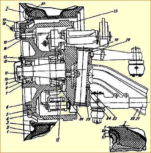
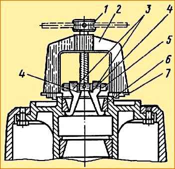
- - remove the outer cover 4 (Fig. 5) with the gasket;
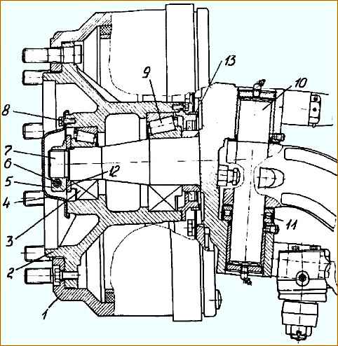
- - unscrew the bolt 6 of the terminal nut securing the hub and unscrew the terminal nut 5, remove washer 12;
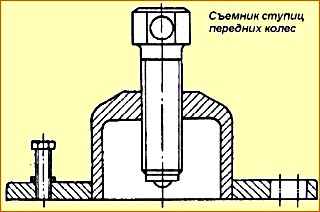
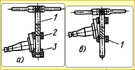
- - remove hub 2 with brake drum 1 without damaging the collar (the puller is shown in Fig. 6);
- - remove the adjusting lever, pad release springs, brake pads and remove the expansion fist;
- - remove the caliper and brake flaps;
- - remove the kingpin plugs, first removing the spring rings;
- - press out the kingpin using a press;
- - remove the steering knuckle 7 together with the thrust bearing 11;
- - press the upper and lower sealing rings out of the steering knuckle;
- - install hub 2 with drum 1 on the workbench;
- - remove the cover with the cuff and take out the cuff;
- - remove the inner tapered roller bearing 9 and press out the outer ring using a puller (Fig. 7);
- - turn the hub over and press out the outer ring of the outer tapered roller bearing 3.
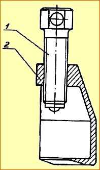
The tie rod end puller is shown in Fig. 8.
- 1. Unscrew and unscrew the nut securing the steering linkage pin.
- 2. Insert the puller slot between the tip and the lever until the puller notch stops in the ball pin.
- 3. By rotating the screw, remove the ball pins of the rods.
Checking the technical condition of parts
Before checking the technical condition of the removed front axle parts, they must be thoroughly washed.
For washing steel and cast iron parts, it is advisable to use alkaline solutions. After this, rinse the parts in soft warm water and then dry.
All parts must be carefully checked for wear, cracks, breakage and deformation. During assembly, damaged parts should be replaced.
Characteristic defects of the steering knuckles are: wear of the bimetallic pin bushings and wear of the bearing journals.
Replace the pin bushings when the gap between the pin and bushing exceeds 0.1 mm. After pressing in the new bushings, expand them to a diameter of 50+0.082 mm (Fig. 1, 5).
Ream out the bushings “in line” using a special reamer that has guides to ensure alignment of the bushing holes.
When unrolling the bushings, do the following:
- - press the bimetallic bushing 2 (Fig. 9, a) of the king pin into the steering knuckle and place the special guide bushing 3 into the second hole for the pin bushing;
- - unfold the bimetallic bushing of the king pin;
- - remove the guide sleeve and press in the second bimetallic pin bushing in its place;
- - unfold the second pin bushing (newly pressed), while passing the cutting part of the reamer through the previously deployed (first) pin bushing, which serves as a guide for the second bushing (Fig. 9, b).
Wear of the bearing journals is allowed: for the outer bearing up to a diameter of 49.94 mm (Fig. 1, 5). for internal diameter up to 69.93 mm.
If there are gaps in the hinge joints of the steering linkage rods, disassemble the hinges and remove worn parts.
The runout of the working surface of the brake drum relative to the seating surfaces of the outer rings of the tapered bearings should be no more than 0.2 mm.
Brake drums are bored together with the hub.
The main defects of the hub are cracks on the ribs, wear of the hub seats for bearings and thread failures M 8 x 1.
Cracks on the ribs are repaired by welding, having previously cut the crack along the entire length at an angle of 90 - 120˚ to a depth of ⅔ of the thickness of the fin.
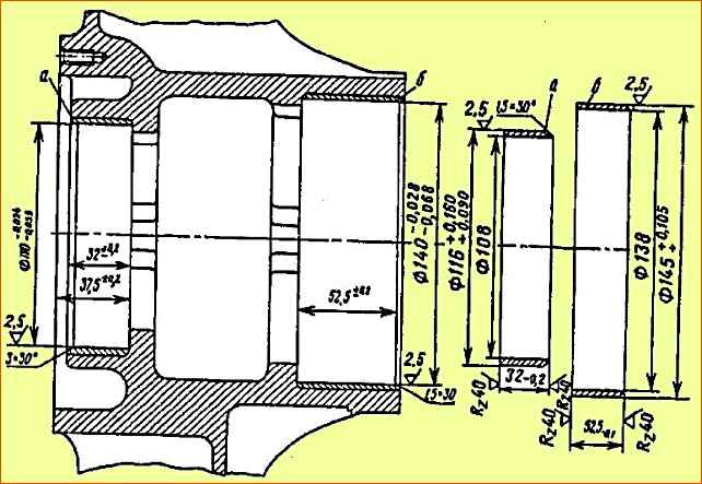
Worn hub bearing seats are restored by installing repair bushings (Fig. 10). The bearing housings are bored to a depth of 2.5 - 3 mm.
The repair bushing is made from a cast iron billet, steel pipe or rolled strip steel, which is pressed into the hub with an interference fit of 0.05 - 0.16 mm, and then bored to the nominal size.
If the M 8 x 1 thread is worn out or broken, the hole is drilled to a diameter of (10.1 ± 0.1) mm, an M12 thread is cut, the screw is screwed in flush with the plane of the base metal, and then the screw is cored at three opposite points.</ p>
Assembling the front axle
Assemble the front axle in the reverse order of disassembly.
Particular attention should be paid to the reliability of fastening the steering ball pins, steering rod arms and brake calipers to the steering knuckles.
If the connection of the ball pin with the lever after tightening with a torque of 215-245 Nm (22-25 kgf.m) is felt, then it is necessary to replace the worn parts.
Assemble the pivot device in the following sequence:
- - using a mandrel, press the radial sealing rings into the upper and lower eyes of the steering knuckle with pressed-in bimetallic bushings so that the sealing edge of each ring is directed towards the throat under the beam;
- - heat the beam head to 150 °C using an inductor;
- - install a plug with an O-ring lubricated with grease into the hole in the upper eye of the knuckle and secure with a spring ring;
- - install the steering knuckle together with the thrust bearing a tenon filled with Litol-24 lubricant onto the head of the beam without noticeable axial play (a gap of 0.05-0.3 mm is allowed), which can be eliminated using adjusting shims of the required thickness, and using a centering mandrel, align the axis of the assembled package with the axis of the beam ;
- - remove the centering mandrel and insert the king pin, ensuring a gap between the top plug and the king pin of 1.7-2.6 mm;
- - install a second plug with an O-ring lubricated with grease into the hole in the lower eye of the steering knuckle and secure with a spring ring;
- - inject the bearings through the grease nipples until grease appears through the safety valve;
- - check the moment of rotation of the steering knuckle relative to the beam. It must be at least 14.71 Nm (1.5 kgf.m).
Install the hub in the following order:
- - before installing the hub, lubricate its internal cavity between the bearings with Litol24 grease.
Lubricate the tapered roller bearings generously, filling all the free space between the rollers with grease - assemble the hub with the inner bearing, cap and cuff and outer race of the outer bearing and install it on the steering knuckle;
- - insert the outer bearing into the hub.
Perform the final installation of the hub with bearings on the steering knuckle, avoiding its transfer;
- - install the washer with the flat on the steering knuckle, aligning the flats in the washer and on the steering knuckle;
- - tighten the terminal nuts with a torque of 225-235 Nm (23-25 kgf.m) until the hub rotates tightly, then unscrew the nut 80-90˚.
Check that the hub rotates easily without axial play (the clearance in the bearings should be within 0.02-0.08 mm).
Secure the bearing mounting nut with a bolt within 49-68 Nm (5-7 kgf.m).
Reinstall the front axle in the reverse order of removal.
After installing the front axle, check the wheel angles.
The steering angles are adjusted by screwing (unscrewing) the thrust bolt into the threaded holes on the steering knuckles.
Check wheel alignment.
")

")
")
")
")
")
")
")