On MAZ vehicles with engines from the Yaroslavl Motor Plant (YaMZ), the following generator sets (GS) are installed: G273V1 - 45 A, 1312.3771 - 50 A, 6582.3701 - 80 A and 3112.3771 - 80 A
It is possible to install a generator 3232.3771, the distinctive feature of which is the absence of an excitation terminal.
Self-excitation of the generator occurs at a rotor speed of no more than 1200 min.
Technical characteristics, design and maintenance features of the generator 3232.3771 are given below.
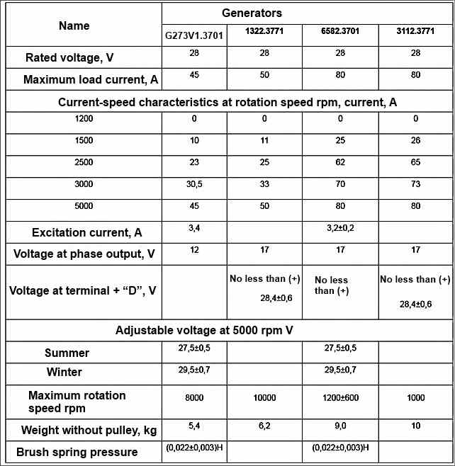
For technical characteristics of generator sets, see the table.
During operation, in order to avoid failure of the generating set, it is prohibited:
- a) disconnecting the wire from the positive terminal of the generator or disconnecting the battery with a ground switch while the generator is running;
- b) checking the serviceability of the generator set by closing the terminals “+”, “B” and “O”, “D” with jumpers to ground and to each other;
- c) check the serviceability of the electrical circuit and individual wires with a megger or a light bulb powered by a voltage above 26 V.
- 2. When installing batteries on a car and connecting them, it is necessary to strictly observe the polarity (“+” to the circuit, “-” to ground).
- 3. Check the tension of the drive belt and the reliability of the connection of the wires to the generator set when the engine is not running and the batteries are disconnected.
- 4. When washing the car, avoid direct contact of water with the generator set.

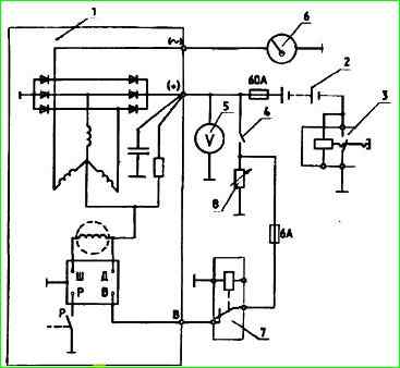
Scheme for connecting the G273V1 generator set to the vehicle’s on-board network: 1 - generator set; 2 - batteries; 3 - ground switch; 4 - starter and instrument switch; 5 - voltage indicator; 6 - tachometer; 7 - generator blocking relay; 8 - load
Scheme for connecting the G273V1 generator set to the vehicle’s on-board network (Fig. 1)
All generator sets consist of self-excited synchronous generators, rectifier units and voltage regulators.
The excitation winding (0 V) of the G273V1 generator is powered from the zero point of the stator winding with a voltage of 14 V.
To improve excitation, a feed resistance is included in the OF circuit. Generator OV 1312.3771; 3112.3771; 6582.3701, powered by additional 28 V diodes.
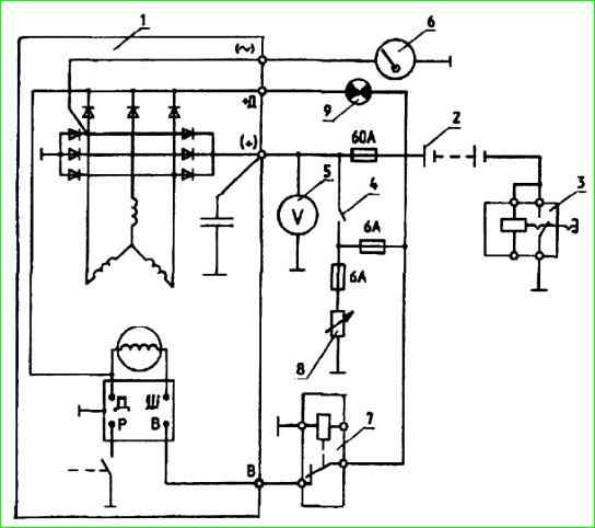
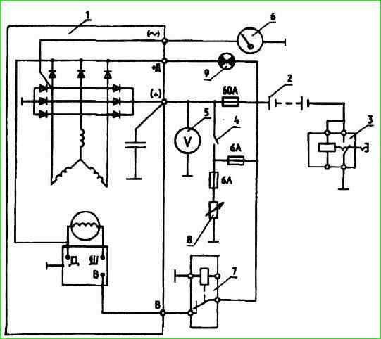
Generators with additional diodes have a battery charge indicator lamp, indicating the serviceability and operation of the generator set.
When the starter switch and instruments are turned on, the lamp lights up if the main unit is working.
After the engine starts and the generator is excited, the lamp goes out.

Scheme for connecting the 65.3701 generator set to the vehicle’s on-board network: 1 - generator set; 2 - batteries; 3 - ground switch 4 - starter and instrument switch; 5 - voltage indicator; 6 - tachometer; 7 - generator blocking relay; 8 - load; 9 - battery charge indicator lamp
Scheme for connecting the generator set 6582.3701 (Fig. 2)
On vehicles equipped with an electric flare device (EFD) to facilitate starting a cold engine, the generator is blocked (the power to the voltage regulator is turned off).
This is necessary in order not to damage the ECU spark plugs, since after the generator is excited, the voltage in the vehicle’s on-board network will be at least 28 V, and the EPI system is designed for a voltage of 24 V.

Connection diagram for generating sets 1322.3771. 3112.3771 to the vehicle’s on-board network: 1 - generator set; 2 - batteries; 3 - ground switch; 4 - starter and instrument switch; 5 - voltage indicator; 6 - tachometer; 7 - generator blocking relay; 8 - load; 9 - battery charge indicator lamp
Connection diagram for generator set 1312.3771; 3112.3771 (Fig. 3)
All generator sets have a phase output for connecting a tachometer.
Voltage regulators for generator sets G273V 1 and 6582.3701 have seasonal adjustment.
When the outside temperature is 0˚ and above, the seasonal adjustment switch (SAD) must be in the “Summer” position (L) and the seasonal adjustment screw must be turned out all the way.
When the outside temperature is below 0 °C PNR should be in the “Winter” position - the screw is screwed in all the way.
The voltage regulators of generator sets 1312.3771 and 3112.3771 do not have seasonal adjustment, but have temperature compensation.
Technical characteristics of generator sets


