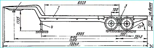
Two-axle semi-trailer MAZ-938 (Fig. 1) with metal flooring with a load capacity of 13 tons, and MAZ-938B (Fig. 2) with an extended frame without flooring with a load capacity of 13.5 tons
The semi-trailers are designed for installation of various equipment and operation on various types of roads, including exits and short-term off-road driving. The diameter of the kingpin is 50.8 mm.
The main traction vehicle for towing is the KrAZ-255V tractor unit, etc.
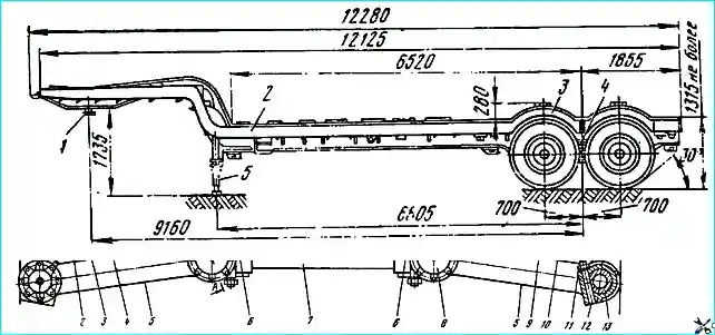
The frame of the MAZ-938 semi-trailer is a welded structure made of sheet metal and stamped sections.
The main load-bearing elements of the frame are made of low-alloy steel.
The front part of the frame is raised above the fifth-wheel coupling of the tractor compared to the main load-bearing surface of the frame.
The frame side members are I-section, welded, with an increased wall height in places of maximum loads.
To reduce stress and increase wall rigidity, corner reinforcements are welded at the frame transition point. The side beams of the frame are stamped, channel section.
The beams and side members are connected by cantilever cross members of variable cross-section, made with stamped holes to reduce the weight of the frame.
At the front, a roll plate is welded to the side members, on which a kingpin socket with a pressed kingpin is welded between the cross members.
Brackets for fastening the support devices are welded to the side member wall at the transition point.
At the rear of the frame, the balance beam suspension brackets are attached to the side members with 16x52 mm rivets, connected in pairs by pipes, the balance beam axle brackets and the suspension buffer brackets.
Mooring eyes are welded to the side members, which serve to secure the semi-trailer during its transportation by various types of transport.
For storage tool and accessories between the side members in the transition area, a tool box is fixed.
The upper surface of the frame is covered with welded ribbed steel flooring, which increases the strength of the frame and ensures ease of movement of cargo along the frame during loading and unloading operations.
In the area of the semi-trailer wheels, the frame beam is cut and connected to the side member with crossbars and beams for fastening the sliding wheel arches.
The frame of the MAZ-938B semi-trailer is the same in design as the MA3-938 frame. The difference is as follows:
- - greater length of the side members and frame beams, which increases the length of the loaded part to 9160 mm;
- - flooring and fastening parts for the wheel arches are not installed;
- - the total length of the frame is 13040 mm.
The diameter of the kingpin for the grips of the fifth wheel device of the tractor is 50.8 mm.
Maintenance and repair are the same as for the frame of the MAZ-5245 semi-trailer, except that if cracks appear in the places where the flooring is welded, it is necessary to clean the damaged areas and weld them with an electric arc welding electrode of Ø 2-3 mm.
Suspension
Device. The semi-trailer uses independent lever spring-balance suspension.
The design of such a suspension consists of two systems: lever and spring-balance.
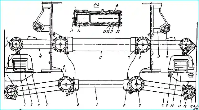
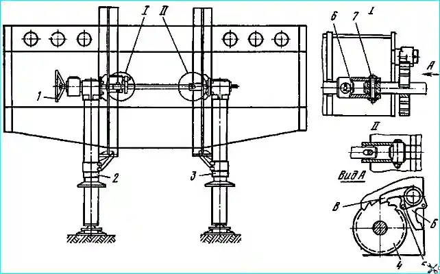
The lever suspension system (Fig. 3) provides independent suspension of each wheel, which is necessary to create good adaptability of the wheels to road irregularities.
Each wheel has a guide device, which is a trapezoidal four-link formed by the suspension bracket 6, the lower 5 and upper 18 levers and the suspension stand 1.
The guide device provides the ability to move the wheel only in the vertical plane, perceives and transmits pushing forces from the frame to the wheels and the braking torque from the wheels to the frame.
The levers 5 and 18 of the suspension are connected to the wheels of the semitrailer through the stand 1, to which the wheel journal is attached. The levers are connected to the rack by means of pins 13.
The suspension levers are connected to the frame via the suspension bracket 6. The levers are connected to the bracket by means of axles 8.
The axles and pins are locked from turning in the bracket and the rack by wedges 16 and 12, secured by nuts 11.
Bronze bushings 21 are pressed into the holes of the levers for the pins and axles, for the lubrication of which oilers 19 are provided. For better distribution of the lubricant along the bushing, a screw groove 5 mm wide and 1 mm deep is made on its inner surface.
Sufficient rigidity of the lever suspension system is ensured by the bracket pipes: the upper 17 with a diameter of 106 mm and the lower 7 with a diameter of 68 mm, which are pressed into the brackets 6.
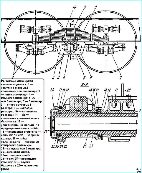
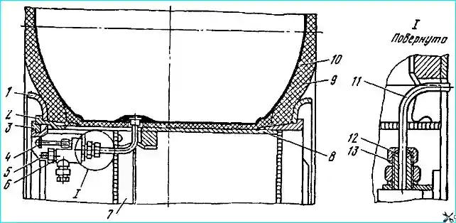
The spring-balance part of the suspension (Fig. 4) ensures uniform load distribution between the wheels located on one side of the semitrailer.
The spring 8, which serves both as a balancer and an elastic element, is located with its ends between the upper and lower arms and rests on spherical supports 7, which are mounted on support brackets 2 (see Fig. 3).
The spherical surface of the supports 7 (see Fig. 4), mating with the lower main leaf of the spring, sharply reduces leaf wear.
Support brackets 2 (see Fig. 3) are pressed into the wheel journals and welded to them.
The downward movement of the wheel when they hang is limited by brackets 1, limiters 4, fixed to support bracket 2.
The spring is fixed with its middle part to balance beam 6 (see Fig. 4), which has a platform for installing the spring. At the ends of the platform, lugs are cast to limit the lateral displacement of the spring.
The hole in the balancer body is stepped: for bushings 27 — 132-0.08 mm in diameter and for seal 15 — 175 + 0.08 mm in diameter.
Six holes with M8 threads are drilled on the outer flange of the balancer for fastening cover 4.
A sealing gasket 25 made of 0.8 mm thick cardboard is installed between the balancer and the cover.
The cover has a threaded hole, closed with plug 19, for pouring oil into the internal cavity of the balancer.
Cover 5 should be installed so that the hole for the plug is above the axis balancer.
The hole for the plug determines the oil level in the balancer, and therefore it is not allowed to change the position of the cover.
The balancer with two bronze bushings pressed into it swings relative to the axis 26 of the balancer.
The balancer is fixed from axial displacement by thrust rings 16 and 17, spacer sleeve 14, nut 18, lock 22 and lock 23 washers and lock nut 20.
The nut is tightened so that the balancer can be turned by hand.
A pin is pressed into the hole in the body of nut 18, protruding above its surface by 4.5 ± 0.5 mm.
A lock washer 23 is installed on the pin and the balancer axis, the protrusion on the inner the hole of which enters a groove milled along the threaded neck of the axle.
The lock washer 22 of the lock nut is installed in the hole of the lock washer 23 with a special extrusion, after which the lock nut 20 is screwed onto the axle. The whisker of the lock washer is bent onto the edge of the lock nut.
The bushings 27 of the balancer are made of bronze and are finally machined after pressing into the balancer.
To ensure optimal distribution of the lubricant along the comparatively long The balancer axle journal has 1 mm deep screw grooves on the surface of the bronze bushings.
The balancer axle is made of 127Лх24—45 steel pipe.
The journals for the holes in the brackets have a diameter of 124-0.08 mm, and the journals for installing the balancers have a diameter of 122-0.06 mm.
Brackets 2 of the balancer axle are attached to the semi-trailer frame using bolts 11.
The brackets are pressed onto the journals of axle 26 and welded to it through windows located on the walls of the lug for the hole for the axle journals.
Protection from dust and dirt on the rubbing surfaces of the balancer is carried out on one side of the balancer using a cover 4 with gasket 25, and on the other - oil seal 15 with sealing ring 12 and safety washer 13.
Upward movement of the wheel is limited by the buffer bracket 15 (Fig. 3) mounted on the side member, against which the platform of the upper suspension arm rests.
A rubber buffer 14 mounted on the balancer bracket serves to soften impacts.
When the wheel moves upward, the spring rotates on the balancer axis until it stops against the protrusion on the balancer bracket.
The wheel then moves upward due to the deformation of the spring until it stops against buffer 14.
The spring is fastened to the balancer using two U-bolts 10 (see Fig. 4). A cover plate 9 is installed between the stirrups and the spring.
The inner surface of the cover plate is made along the radius and fits tightly to the spring.
Two transverse grooves are provided on the outer surface of the cover plate, fixing the relative position of the stirrups.
A hole is drilled in the center of the cover plate to accommodate the nut of the spring center bolt. The ends of the stirrups are secured in the balancer holes with high nuts.
The spring consists of a pack of leaves that are pulled together with a central bolt.
The main leaves of the spring have the same length and are fixed to each other with a press around the perimeter of the hole for the central bolt in such a way that the projection of the upper leaf enters the recess of the lower one.
Two clamps made of strip steel riveted to the ends of the spring leaf serve to prevent lateral displacement of the leaves.
A 104 mm long spacer tube is installed between the clamp cheeks with a tie bolt to prevent bending of the ends of the clamp.
Maintenance of the suspension consists of checking the tightening of all bolted connections.
It is especially necessary to monitor the fastening of the balancer axle brackets to the semitrailer frame and the tightening of the stirrups springs, as well as the condition of the fastening parts of the suspension linkage system elements.
In order to prevent the spring center bolt from shearing off, tighten the U-bolt nuts with a torque of 60–65 kgf/cm.
When installing the balancer on the axle or loosening its fastening, first tighten the balancer nut until it stops, and then loosen it by 1 ∕12 turns, while the balancer should turn on the axle with the force of your hand.
After this, secure the nut with a lock washer 23 (see Fig. 4), put on the lock washer 22 and tighten the lock nut 20, locking it with the lock washer.
In no case should the semitrailer be operated with increased axial play of the balance beams, as this may lead to stripping of the threads on the axle and nuts.
In addition, maintenance of the suspension comes down to mandatory lubrication of the spring sheets with graphite grease during their next disassembly, adding oil to the balance beam cavity and lubricating the suspension arm pins.
Repair. Disassembly of the suspension of the left and right wheels is carried out simultaneously.
To disassemble the suspension, it is necessary to install the rear part of the frame on the trestles, remove the wheels, limit brackets, spring U-bolts and springs.
If it is necessary to remove the balance beam, unscrew the drain plug, turn the balancer with the drain hole down and drain the oil from the balancer, then remove the balancer cover, unscrew the lock nut, remove the lock and lock washers, unscrew the nut and remove the balancer.
The balancer axle with the brackets in the assembly is removed in case of breakage of the axle or the balancer bracket.
If it is necessary to disassemble the guide device, it is necessary to unscrew the nuts of the pin wedges and axles of the upper and lower arms, knock out the wedges, remove the caps of the pins and axles of the upper and lower arms, knock out the pins and axles of the arms.
During operation, breakage and cracks of the sheets, breakage of the center bolt, breakage of the clamps, wear of the ends of the main leaf may occur in the springs.
Spring sheets that have cracks or wear from the mating sheet more than 1 mm should be rejected.
Broken center bolts and the clamps are subject to replacement.
Cracks on the clamps are welded and cleaned flush with the main surface. Worn lower main sheets are swapped with the second main sheets.
Main sheets with wear of more than 6 mm are replaced with new ones.
If there are cracks and minor wear, the spring sheets can be remade to shorter ones and used for for spring assembly.
Sheets with residual deformation (sagged) are straightened, ensuring the dimensions of the sheets.
Step ladders with cracks or thread stripping are replaced with new ones, and cracks in the spring linings are welded and cleaned.
When assembling a spring, the following requirements must be met:
- - spring sheets must fit tightly to each other, gaps between the sheets of the assembled spring are allowed over a length of no more than ¼ of the total contact length of two adjacent sheets, while the gap size should not exceed 2 mm.
Adjacency of the working ends of the sheets is mandatory.
After assembly, each spring is subject to subsidence to a deflection of 160 mm from the free state (under a load of approximately 19,500 kgf).
Repeated load of the same magnitude should not cause residual deformation.
From the control load of 7850 kgf, the deflection should be 88 mm. The ends of the springs are supported on cylindrical supports with a radius of 100 mm;
- - lubricate the rubbing surfaces of the sheets with graphite grease before assembly;
- - after tightening the nuts, punch or rivet the threaded ends of the clamp bolts and center bolts.
The spring clamps must not impede the free movement of the sheets during spring operation;
- - the displacement of the spring sheets in width relative to the first sheet is allowed to be no more than 2.5 mm.
The assembled spring is subjected to settling, after which it is sorted into two groups depending on the deflection: the 1st group includes springs with a deflection of 123 +10 mm (they are marked with white paint), the 2nd one - with a deflection of 123-10 mm (they are not marked).
Only one group of springs is installed on a semi-trailer.
The bushings, balancer axle, balancer seals, suspension arm pins and axles wear out in the balancer suspension and wheel guide device.
Thoroughly clean bronze bushings from old grease and dirt. Thoroughly clean rust, burns and bronze galling with sandpaper.
Worn balancer bushings are pressed out and replaced with new ones. New bushings after pressing are bored to size 122+008 mm.
Possible suspension malfunctions and how to fix them
Cause of malfunction - How to fix
- 1. Shift of spring leaves:
Center bolt is cut off - Replace the center bolt
- 2. The end of the spring touches the support bracket:
Worn ball joint - Replace the ball joint
- 3. Oil leak in the balancer:
Worn oil seal or unusable gasket - Replace the oil seal or gasket
- 4. No oil in the balancer without leakage:
Oil from the balancer goes into the balancer axle - Restore the tightness of the balancer axle plug by welding
- 5. Suspension strut swing in the lever:
Worn thrust washers - Replace thrust washers
- 6. Increased spring settlement:
- - Breakage of individual sheets - Replace broken sheets
- - Loss of elasticity of sheets - Straighten sheets
Proceed similarly with lever bushings with boring to size 90 +0.07 mm.
Welding cracks at the weld points of the balance shaft to the suspension bracket are not a rejection sign and can be eliminated by additional welding.
The working edge of the oil seal must be sharp, without dents, cracks or other damage.
Oil seals with the specified damage must be replaced with new ones. The sealing rings and gaskets must be intact.
When assembling the suspension balancer with the axle, the following requirements must be met.
Install the safety washer 13 (see Fig. 4), the spacer sleeve 14 with the sealing ring 12 on the balancer axle, install the thrust ring 16 and the oil seal 15 in the balancer, then, having lubricated the axle of the balancer bushing with transmission oil, install the balancer on the axle.
After installing the thrust ring 17, tighten the balancer nut so that the balancer rotates on the axle with a slight hand force without noticeable longitudinal play.
Install the lock washer so that its hole coincides with the nut pin.
Install the lock washer of the lock nut with the protrusion in the hole of the lock washer nuts.
Tighten the lock nut until it stops and lock it by bending the edge of the washer onto the edge of the nut.
Pour MT-16P oil (GOST 6Z60-58) into the assembled balancer up to the lower edge of the filler hole (0,6-0.7 l each).
The guide device is assembled and the spring is installed on the semi-trailer in the reverse order of disassembly and removal.
The tightening torque of the nuts of the bolts securing the balancer brackets to the frame should be 12-14 kgf•m.
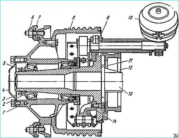
Axles and hubs
Axle 11 (Fig. 5) of the wheel is fastened with bolts to the strut 12 of the independent suspension of the semi-trailer.
The support bracket 13 of the spring is pressed into the axle. Brake support 14 is attached to the axle with bolts
Hub 1 of the wheel is mounted on two tapered roller bearings.
The wheel is fastened to the hub with nuts 6, clamps 7 and bolts.
Maintenance of the axle and hub is the same as for similar parts of the MAZ-5245 semitrailer.
Wheels and tires
Device. The semitrailer is equipped with diskless wheels (Fig. 6) measuring 440-553 mm with 1300x530x533 tires of the VI-3 model.
The tires are 12-layer low-pressure pneumatic cylinders with a directional tread pattern.
The tire is clamped between the side rings 1 using the lock ring 3.
Valve 11 wheel chambers are connected to the centralized tire inflation valve using a cap nut 13.
The connection is sealed by pressing the rubber sealing ring 12.
For the purpose of unification and interchangeability of the tractor wheels with a semi-trailer, a wheel valve 6 is installed on the semi-trailer wheels, which is part of the centralized tire pressure regulation system on the tractor.
The tires of the semi-trailer wheels are inflated through the valve 4 of the individual tire inflation system. Plug 5 must be screwed in all the way.
Maintenance of wheels and basic rules for operating tires are the same as for the MAZ-5207V trailer.
Installation and removal of wheels
To remove a wheel from a semitrailer, use a hydraulic jack to lift it 5-10 cm above the ground, unscrew the hub bolt nuts and carefully, without touching the threaded part of the bolts, remove the wheel, having first moved the sliding wheel arch.
Install the wheels in the reverse order.
When installing the wheel on the hub and securing it, it is necessary to ensure that there is no end runout of the wheels, which is controlled by the fit of the mounting ring 7 (see Fig. 6) on the hub.
The difference in fit sizes of diametrically opposite hub spokes should not exceed 4 mm.
Tire mounting and dismounting on the rim is performed using two mounting blades.
The mounting procedure is as follows.
Insert the tube 10 into the tire, having previously powdered them with talc, insert the rim tape and slightly inflate the tube with air.
Place the rim 8 of the wheel on a clean floor with the groove under the valve facing up, put the bead ring 1 on, and then the tire 9 on the rim.
In this case, the tube valve should come out through the groove of the rim and be located in the center of the hole in the protective casing welded to the rim.
Put on the bead ring 1, insert the seat ring 2 so that the locking protrusion on the seat ring is in the widened part of the valve groove.
Insert the curved end of the mounting blade into the lock groove of the rim and push the seat ring down, thereby releasing the lock groove of the rim for seating the lock ring in it.
Insert one end of the lock ring 3 into the lock groove of the rim and, using the straight end of the mounting blade inserted between the rim and the lock ring, press the ring towards you until it is fully installed.
Fasten the wheel crane 6 to the protective rim casing, for which:
- - remove the valve from the casing hole and put on it a union nut, conical washer, sealing ring, valve mounting nut and spring washer;
- - insert the wheel crane into the casing hole and insert the end of the valve into the cavity of the crane, preventing dust and foreign objects from getting in;
- - put on the spring washer, screw on the nut securing the crane to the casing without tightening it, screw on union nut. In this case, the sealing ring and conical washer must enter the nut without distortions or jamming;
- - tighten the valve mounting nut and union nut (excessive tightening of the union nut can lead to deformation of the valve).
Close the wheel valve (if it was open), screwing in the shut-off plug 5 with a special key and inflate the tire to the required pressure through the individual inflation valve.
When inflating a tire in a garage, the assembled wheel must be placed in a special grid, and when performing this operation outside a garage, the lock part of the wheel must be directed away from the driver and nearby people.
Cold tires must be warmed up to positive temperature before installation temperature.
When installing tires with a directional tread pattern (high cross-country ability), ensure that the direction indicators of their rotation (arrows on the sidewalls of the tires) coincide with the direction of rotation of the wheels when the car is moving forward.
It is recommended to dismantle the tires in the following order.
Release the air from the tire, remove the wheel crane 6, insert the curved end of the mounting blade into the stamped groove of the seat ring 2 and seat the tire bead together with the bead ring.
Repeat this operation on each groove, sequentially around the circumference of the wheel, completely remove the tire bead from the seat shelf of the ring.
Remove the lock ring 3, for which:
- - insert the straight end of the mounting blade into the groove of the lock ring and press the seat ring down;
in the resulting the gap between the lock and seat rings, insert the curved end of the second mounting blade and, successively pressing it along the circumference of the wheel, push the seat ring down;
- - with the straight end of the mounting blade, press the lock ring and remove it from the groove, and with the curved end of the second mounting blade, successively remove the lock ring from the groove until it is finally removed.
Insert the curved end of the mounting blade between the bead ring and the flange of the seat ring and press the seat ring successively along the circumference of the wheel until it is finally removed.
Remove bead ring 1, turn the wheel over and remove the tire bead from the seat shelf.
Place the wheel at an angle to the wall and, inserting the curved end of the mounting blade between the bead ring and the flange of the rim, slightly press the rim along the circumference.
Holding the rim with both hands, remove it completely, having first sunk the valve into the groove of the rim.
If the rim tape sticks (burns) to the rim, turn the wheel over, insert the straight end of the tire iron between the rim and the rim tape and, moving it around the circumference, completely release the rim tape.
Adjusting wheel bearings. At each TO-2, it is necessary to check and, if necessary, adjust the tightening of the wheel hub bearings.
Adjust the bearings in the following order.
Lift the wheel with a jack so that the wheel tire does not touch the ground.
Unscrew the hub cover mounting bolts, remove cover 4 (see Fig. 5). Loosen the lock nut, remove the lock washer 3 and check if the wheel rotates freely.
If the wheel rotates with difficulty, it is necessary to find out the cause and eliminate it (interference with the brake linings, bearing failure).
Tighten the nut until it stops with a force of approximately 40 - 50 kgf using a wrench with a 500 mm long handle.
When tightening the nut, it is necessary to turn the wheel to correctly position the rollers on the bearing races.
Loosen the nut by one or two slots in it until the tab of the lock washer aligns with the slot of the nut, then check the rotation of the wheel; wheel - should rotate freely, but without axial play.
Install the lock washer and tighten the lock nut until it stops.
After adjusting the tightening of the wheel hub bearings, check the correctness of the adjustment by heating the hub cap during the first 100 km of travel.
Heating the hub to a high temperature (the hand cannot withstand prolonged contact) is not allowed and must be eliminated by re-adjusting the bearings or brakes.
Repair. Tires and tubes are repaired by vulcanization. Cracks may appear on the rims of the wheels during operation. The cracks are cut, welded and cleaned flush with the main surface.
To prevent the crack from spreading, its ends are drilled before welding.
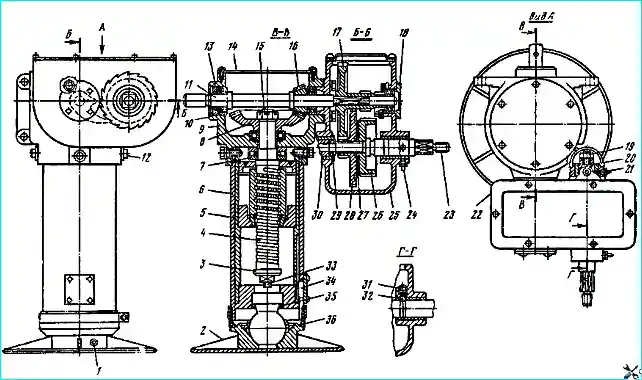
Support device
Device. The support device (Fig. 7) is two screw jacks (Fig. 8) located in the front part of the semitrailer and connected to each other by an intermediate shaft.
The right support device differs from the left one by the presence of a two-speed gearbox.
The presence of a two-speed gearbox ensures accelerated lifting and lowering of the support device plates at idle.
The extreme upper position of the retractable support device post is limited by the bushing on the fixed post 6. The extreme lower position is limited by the shoulder 3 of the screw.
To lift the semitrailer (i.e. extension of the movable stand to the lower position) it is necessary:
- - place the semitrailer on a horizontal platform and, using steering wheel 1 (see Fig. 7), pull the drive shaft 23 (see Fig. 8) towards you until it stops, until ball 32 enters the annular groove, thereby engaging the overdrive gear;
- - turn the steering wheel counterclockwise to lower the support device until support plate 2 touches the ground;
- - engage the downshift gear by using the steering wheel to push the drive shaft forward until it stops and, turning the steering wheel counterclockwise, lift the semitrailer.
Lower the semitrailer or set the support device to its original position in the reverse order.
When raising the semitrailer (lowering the support devices), pawl 5 (see Fig. 7) must be engaged with the ratchet of the intermediate shaft 4.
When lifting the support devices to the transport position, the pawl must be disengaged.
Working in second gear (the drive shaft is pulled out to the limit) after the plate has touched the ground (regardless of whether the semitrailer is loaded or unloaded) is strictly prohibited.
In exceptional cases, when it is necessary to uncouple the tractor from the semitrailer on an uneven surface, the semitrailer is designed to misalign the operation of the support devices.
If, when lowering the support devices, the support plate of the left support device touches the ground, and the right one does not reach the ground by more than 50 mm, it is necessary:
- - engage the pawl 5 with the ratchet of the intermediate shaft 4, remove the pin 7 in the area of the right support device and use the steering wheel to lower the right support device until the plate touches the ground;
- - insert pin 7 and use the steering wheel to raise the semitrailer to the required height.
If the plate of the right support device has touched the ground, and the left one has not reached the ground by more than 50 mm, it is necessary to:
- - engage pawl 5 with the ratchet of intermediate shaft 4, remove pin 7 in the area of the right support device and use the steering wheel to raise the right support device by an amount equal to the distance between the ground and the plate of the left support device;
- - insert pin 7 and use the steering wheel to lower the support device until it touches the ground, and then raise the semitrailer to the required height.
Further after coupling semi-trailer with a tractor, raise the support devices to their original state (before the misalignment of the support devices).
Maintenance
The support device must be kept clean.
It is necessary to lubricate the points of the support device subject to lubrication in a timely manner, ensure that in the transport position the support plate 2 (see Fig. 8) rested against the protective cap 36 to prevent dirt from getting under the tractor wheels.
In winter, when the semi-trailer is parked without a tractor, wooden pads are placed under them to prevent the support plates of the support devices from freezing.
Before working with the support device, it is necessary to chip off the ice from the support plates.
The bolted connections should be checked in a timely manner and tightened if necessary.
Repair
The support device is usually disassembled when replacing worn or broken parts, as well as to add or replace lubricant.
Disassembly can be carried out partially or completely, depending on which part needs to be replaced.
The disassembly procedure is as follows:
- - install the semi-trailer with the front part on the trestles, remove the support devices from semitrailer and the steering wheel, rotating the drive shaft 23 counterclockwise (see Fig. 8), lower the support plate 2 by 80-100 mm;
- - remove the locking ring 35, take out the support plate together with the ball joint, unscrew the lock screw 33 and the screw bolt, remove the key with the cover 34 and covers 14 and 22;
- - disassemble the drive 23 and driven 11 shafts, unscrew the nut 15, and lightly tapping the end of the screw 4 with a hammer, remove the bevel gear 8;
- - unscrew the bolts 12, remove the housing 9 and the thrust bearing 7, take out the rack 5, unscrew the rack nut and in remove the screw with the nut. The nut with the screw is not disassembled, as it is installed in the kit by the manufacturer;
- - remove two spherical washers.
After disassembling, wash all parts, blow with dry compressed air, lubricate generously and assemble the support device in the reverse order. Fill the crankcase and housings with grease.
Disassembly and assembly of the left support device is carried out in the same way as the right one, without taking into account the additional gearbox.
The left support device does not have a brake device, so when removing it from the semitrailer, it must be lowered until it touches the ground.
Before disassembling the drive shaft, it is also necessary to lower the support device until it touches the ground, since when the shaft is disassembled, the brake device ceases to operate.
The drive shaft or parts located on it can be replaced without removing the support device from the semitrailer. To replace the drive shaft 23 or any part located on it, it is necessary to:
- - remove the rubber cap and cover 22 of the gearbox, unscrew the nut 19 and sleeve 20, remove the thrust bearing 29, unscrew the plug 31 and take out the ball retainer spring;
- - turn the drive shaft 23 clockwise with the handwheel, unscrew it from the gear block 28, remove the drive shaft from the gearbox housing, take out the gear block 28, friction ring 27, brake ratchet 26 and ball 32 from the housing.
The drive shaft should be assembled in the following order:
- - install the drive shaft in the hole in the gearbox housing;
- - install the brake ratchet on the drive shaft, friction ring and gear block;
- - engage the pawl with the brake ratchet and, holding the gear block with your left hand, screw in the drive shaft with your right hand, turning the steering wheel counterclockwise;
- - feed the drive shaft forward until it engages with the gear block of the driven shaft 11, install the ball and the retainer spring, screw in the plug, install the thrust bearing, screw in the sleeve, lock it with a nut and install the cap.
To disassemble the driven shaft 11, it is necessary to:
- - remove the support device, and then the covers 14 and 22;
- - disassemble the drive shaft 23, remove the bearing cover 18 and take out the thrust ring 13;
- - install a bronze or brass drift in the mountains driven shaft from the gearbox housing side and lightly tap the shaft together with the bearing, adjusting linings, bearing cover and felt ring;
- - remove the bearing, adjusting linings, bearing cover and felt ring from the driven shaft;
- - remove the drive bevel gear, key, driven gear block, spacer sleeve and ratchet pawl from the housing;
- - remove the gearbox housing bearing. The inner bearing of the drive bevel gear may not be removed. If it needs to be replaced, unscrew the bolts and remove the gearbox housing together with the adjusting linings 10.
Before assembling the driven shaft, all parts must be washed, blown with dry compressed air and lubricated.
Assembly must be performed in the following sequence:
- - install the key on the driven shaft and engage the leading bevel gear with the driven gear;
- - insert the shaft into the leading bevel gear and bearing, and then install the driven gear block, spacer sleeve and brake ratchet pawl on the shaft;
- - install the bearings in the gearbox housing and the support device housing and tighten the bearing cover 18 until it stops;
- - check the engagement of the bevel gears, adjust with adjusting linings if necessary 10;
- - install the bearing cover with the felt ring and insert the thrust ring 13 into the annular groove;
- - assemble and install the drive shaft, secure the covers 14 and 22.
Gears, bearings, screw, nut, internal machined and all rubbing surfaces of the support device should be generously lubricated with TSIA-TIM-201 grease.
Brake system
The semitrailer is equipped with two brake systems: service and parking. Both systems act on the pads of the wheel brake mechanisms.
The pneumatic drive of the service brake system, wheel brake mechanisms and parking brake are the same as on the MAZ-5205A semi-trailer.
Electrical equipment
The electrical equipment of the semi-trailer consists of one seven-pin and four single-pin sockets for portable lamps, two rear lights that function as stop signals, parking lights, turn signals and wires connecting the electrical equipment of the tractor and semi-trailer.
Possible malfunctions of the support device and how to eliminate them
Cause of malfunction - Method of elimination
When turning the steering wheel, the support device does not lower or rise
The key on one of the bevel gears is cut off - Replace key
The brake of the support device does not hold
Failure of the screw-nut pair - Zam Remove the screw-nut pair
Worn friction ring - Replace friction ring
")

")
")
")
")
")
")
")