Power steering pump for MAZ vehicle
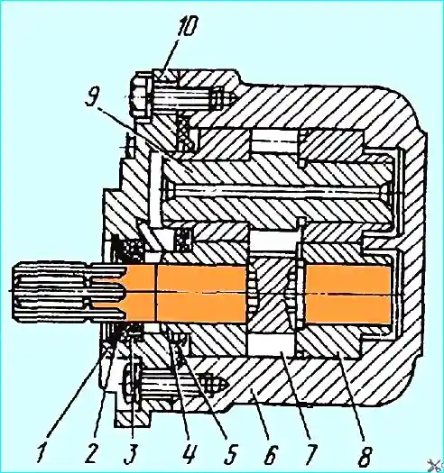
The gear pump NSh-32U consists of a housing 6 (Fig. 1) and two gears located in it: driving 7 and driven 9, rotating in bronze bushings

Fig. 1. Oil pump: 1 — retaining ring; 2 — support ring; 3 — oil seal; 4 — left bushing; 5 — cuff; 6 — housing: 7 — driving gear; 8 — right sleeve; 9 — driven gear; 10 — cover
This sleeve simultaneously provides an end seal for the gears.

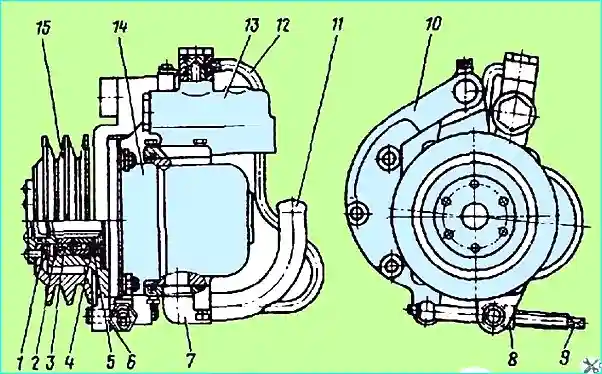
Fig. 2. Oil pump with tensioner and flow and pressure valve: 1 hub; 2, 4, 5 — retaining rings; 3 — bearing; 6 — movable bracket; 7 — suction pipe; 8 — lock nut; 9 — adjusting screw; 10 — fixed bracket; 11 — suction pipe; 12 — oil drain pipe; 13 — flow and pressure valve; 14 — pump; 15 — pulley.
The pump is driven by the crankshaft using V-belts (T-14x13-1000 GOST 5813-76).
The belt tension is adjusted using a tensioner consisting of a fixed bracket 10 (Fig. 2) and an adjusting screw 9 with a lock nut 8.
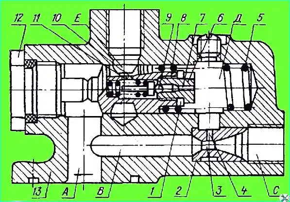
The flow and pressure valve design is shown in Fig. 3.

Fig. 3. Flow and pressure valve: 1 adjusting gaskets; 2 — jet; 3 — central hole in jet; 4, 7 — throttle channels: 5, 10 — springs; 6 plug; 8 — plunger; 9 — ball; 11 — hole in plunger; 12 — plug: 13 valve body; A, B, C, D, E — channels to the cavity in the housing
The flow and pressure valve operates as follows.
The working fluid from the pump under pressure enters the vertical channel A and then through the horizontal channel B, through the central hole 3 in the nozzle 2 to the steering gear distributor.
Since the speed in the central hole 3 of the nozzle 2 is higher than in channel B due to the difference in the flow sections, the pressure in the cavity (D) connected to the central hole will be lower than in channel B, and, consequently, than in the vertical channel A and horizontal channel E.
With an increase in the rotation frequency of the pump gears, the pressure difference in the cavity (D) and in channels A and E increases and when the pump feed is over 31-35 l/min, the plunger 8 moves to the right, compressing the spring 5.
In this case, the working fluid partially returns from the vertical channel A through the tube 12 (see Fig.) to the suction branch 7 of the pump.
Therefore, regardless of the pump rotation speed, the flow rate of the working fluid through the distributor will be no more than 31-35 l/min.
When the pressure in channels A and B and cavity (D) (see Fig. 3) increases to 9810-10790 kPa, ball 9 breaks away from the seat, compressing spring 10.
The working fluid from cavity (D) through the throttle channel of plug 6, through radial hole 11 in the plunger, through the tube, enters the drain.
Since the flow sections of throttle channels 4 and 7 differ slightly, the pressure in cavity (D) practically does not increase.
The increase in pressure in channel A causes plunger 8 to move to the right, as a result of which the working fluid from channel A partially enters the suction branch of the pump through the tube.
Thus Thus, the power steering system is protected from overload.

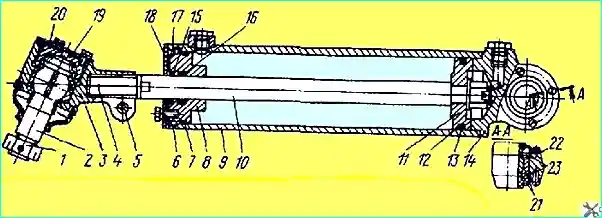
Fig. 4. Power cylinder: 1 — nut; 2 — ball pin; 3 — tip; 4 — pin; 5 — tie bolt; 6 — retaining half rings; 7 — sealing ring; 8 — cover; 9 — pipe; 10 — rod; 11 — piston; 12 sealing ring; 13 — fluoroplastic ring 14 - base; 15 — wiper blade; 16 — cuff; 17 — wiper washer; 18 plate 19 - plug; 20 - cover; 21 — spherical bearing; 22 rubber seal; 23 retaining rings
Power steering pump repair
Removing the pump from the car. To remove the pump, do the following:
- — loosen lock nut 8 (see Fig. 2) and unscrew the adjusting screw, loosening the belt tension;
- - disconnect the hoses;
- — unscrew the bolts securing the fixed bracket to the engine, remove the pump with the tensioner, having first removed the belts.
pump assembly. Disassembly procedure:
- — secure the pump by the fixed bracket 10 in a vice;
- — disconnect the oil drain tube 12 from the flow and pressure valve body;
- — remove the flow and pressure valve and the suction pipe 7 from the pump;
- — mark the position of the pulley 15 relative to the pump body;
- unscrew the nuts and disconnect the pump from the movable bracket 6, marking the position of the pump shaft splines relative to the previously applied mark on the pump body;
- — remove the retaining ring 4 and press out the hub 1 with the pulley 15 from the bearings 3;
- — remove the retaining ring 2, and then the bearings from the movable bracket;
- — unscrew the plug 12 (see Fig. 3), remove plunger 8 and spring 5 from the housing (under the action of spring 5, the plunger should come out of the housing freely);
- — fasten plunger 8 to the non-working surface (fastening along the outer diameter is unacceptable), unscrew plug 6 and remove ball 9 and spring 10 with the guide.
After disassembling, check the condition of the parts.
The end surfaces of the bushings and gears of the pump, the working surface of plunger 8 should not have noticeable burrs, and the cuff 5 (see Fig. 1), gland 3 and sealing gaskets should not have damage.
The splines on the pump shaft and in the hub may have wear of no more than 4.0 mm.
Damage to the pulley grooves, cracks in the brackets of the tensioner are not allowed. devices.
Assembly and adjustment of the pump. Assemble the pump in the following order:
- — fasten plunger 8 (see Fig. 3) and install spring 10 with guide, ball 9, plug 6 with adjusting linings 1;
- — adjust the opening pressure of the ball in a special device with adjusting linings 1.
If before disassembling there was no sharp increase in the force on the steering wheel when turning the wheel in place, then this adjustment can be omitted;
- — install plunger with spring 5 in place and tighten plug 12;
- — install bearings 3 (see Fig. 2) in movable bracket 6 and secure with a retaining ring;
- — press hub 1 with pulley into bearings and install the retaining ring 4;
- — pour 50 cm³ of oil into the movable bracket 6 so that the oil fills the hub cavity;
- — connect the pump (aligning the marks made during disassembly) to the movable bracket, having previously installed the gasket;
- — install the flow and pressure valve in place and connect the suction pipe 7 to the pump, connect the oil drain pipe 12.
Installing the pump on the car. Installation procedure:
- — put the belts on the drive pulleys of the engine and pump and secure the fixed bracket 10 on the engine;
- — use the adjusting screw 9 to adjust the belt tension.
When tensioned correctly, the deflection in the middle part of the belt under a force of 39 N should be within 10-15 mm.
After adjustment, tighten the lock nut 8 and connect the hoses.


