Brake mechanisms are drum type with two internal pads and an easily removable brake drum
On vehicles equipped with ABS, special holes are made in the rear axle brake pads (opposite the tension spring hooks) to allow removal or replacement of brake pads without disassembling the wheel drive.
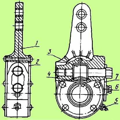
At the end of the expansion cam shaft there is a worm-type adjusting lever (Fig. 1) connected to the brake chamber rod.
By turning worm 3 by the hexagonal head of the axle with a wrench, you can turn the expansion fist, and therefore spread the brake pads, thereby reducing the gap between them and the drum.
To rotate the axis, plate 7 must be released and moved upward.
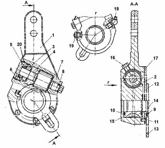
On cars, an adjustment lever with a built-in automatic regulator can be installed (Fig. 2).
To prevent lubricant from entering the brake mechanisms, rubber sealing rings are installed in the brackets of the front and rear brake expansion cams.
Brake chambers are diaphragm, designed to activate the brake mechanisms of the front wheels of the car when the service brake system is activated.
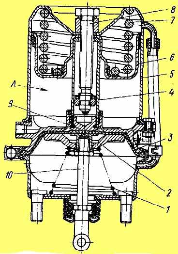
Brake chambers with spring energy accumulators (Fig. 3) are designed to activate the brake mechanisms of the wheels of the rear and middle axles when the service, parking and spare brake systems are engaged.
When the service brake system is turned on, the brake mechanisms are actuated by the rods of 10 diaphragm brake chambers, the design and principle of operation of which is practically no different from the front brake chambers (inlet 11).
When the parking brake system is turned on, compressed air is released from the cavity under the piston 6, which, under the action of the power spring 7, moves down and moves the pusher 4, the latter, through the thrust bearing 9, acts on the diaphragm 3 and the rod 10 of the brake chamber, resulting in the car braking .
When the parking brake system is turned off, compressed air is supplied under the piston 6 through the inlet 12, which, together with the pusher, moves upward, compressing the spring and allowing the brake chamber rod to return to its original position under the action of the return spring 1.
When braking with the spare system, the air from the cylinders of the energy accumulators is partially released to the extent of the required braking efficiency of the vehicle, which corresponds to the intermediate positions of the control valve handle.
Thus, the braking efficiency depends on the angle of rotation of the crane handle.
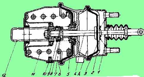
It is possible to install diaphragm brake chambers with a spring energy accumulator and a quick-release device on the car (see Fig. 4).
The quick-release device (QRU) is a spring-loaded fixing sleeve 9, which provides connection of the diaphragm 5 with the rod 4 of the energy accumulator through balls 8.
The chamber is released as follows: remove the cover, insert the pusher 12 (located in the spare parts box) until it stops into the fixing sleeve 9 and press or lightly hit with a hammer.
In this case, the sleeve 9 moves, the balls 8 come out of the groove on the rod 4, the diaphragm 5, under the influence of the spring 11, moves until it stops in the body, spring 1 moves the rod 4, releasing the wheel brake mechanism.
When compressed air is supplied to cavity “A”, the balls 8 fall into the groove of the rod 4 and are fixed by the sleeve 9, while the energy accumulator is blocked.
It is strictly prohibited to independently disassemble spring energy accumulators!
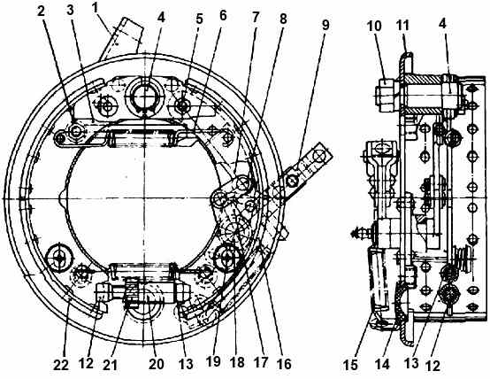
The brake mechanism of the main parking brake system of MAZ-631705, 631708, 642505, 642508, 533605 vehicles is drum (Fig. 5), double servo shoe with lever release of the shoes and a gap adjustment mechanism.
It is attached to the transfer case housing, the brake drum is attached to the transfer case output shaft flange.
The action of the brake is as follows.
When braking, the force from the drive cable is transmitted to the drive lever 9, which, through the intermediate lever 17 and the linkage 8, acts on the shoe lever 7.
When the drum rotates counterclockwise, the driving force from the shoe lever through rod 3 is transmitted to the left shoe 22 and presses it against the brake drum.
In this case, the block, due to friction, is captured by the drum and moves in the direction of rotation, pressing through the adjusting device on the right block 16, and presses it against the drum.
When the brake drum rotates clockwise, the shoe lever 7, resting on the rod 3, transmits the driving force to the right shoe 16 and presses it against the drum.
Due to friction, the block is captured by the drum and is shifted in the direction of rotation, pressing through the adjusting device on the left block 22, and presses it against the drum.
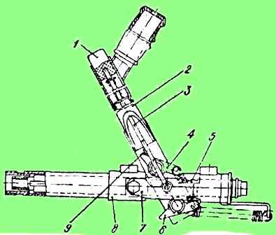
The drive diagram is shown in Fig. 6, the design of the control lever is shown in Fig. 7.
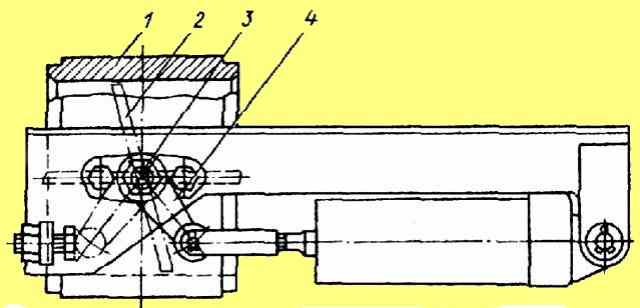
The mechanism of the auxiliary brake system (Fig. 8) is a throttle type with flaps installed in the engine exhaust pipe in front of the muffler.
The mechanism consists of a body and dampers 2, mounted on an axis 3.
A rotating lever 4, connected to the rod of the drive pneumatic cylinder, is also attached to the damper axis.
Lever 4 and the dampers 2 associated with it have two fixed positions.
When the auxiliary brake is turned off, the damper is installed along the exhaust gas flow, and when turned on, it is perpendicular to the gas flow, creating back pressure at the outlet.
At the same time, the fuel supply is turned off using a pneumatic cylinder connected to the engine stop bracket.

The pneumatic cylinder (Fig. 9) is designed to control the flaps of the auxiliary brake system mechanism.
When the auxiliary brake system is turned on, compressed air enters the space above the piston and, overcoming the resistance of the return springs, moves the piston and rod 8, which is connected to the valve control lever of the mechanism.
The piston returns to its original position under the action of the return spring.
Adjusting the brakes
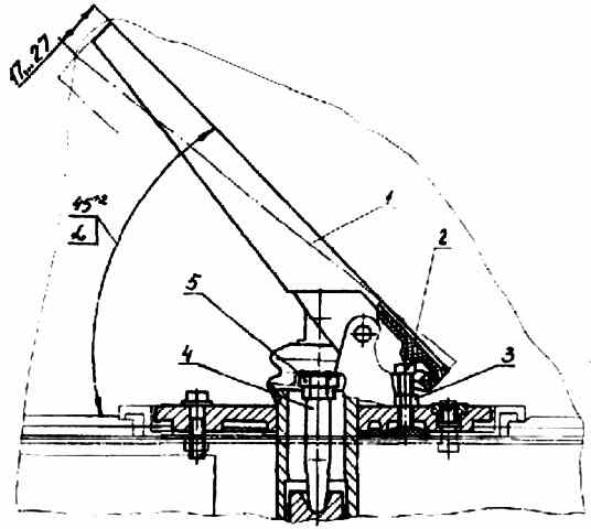
In the brake valve drive (Fig. 10), the angle of 45°+2° is adjusted by bolt 2. After adjustment, tighten nut 3 to a torque of 11.8-15.7 Nm. The pedal free play should be 17-27 mm.
Adjustment is made by changing the length of rod 4. After adjustment, tighten nut 5 to a torque of 23.5-35.3 Nm.
When installing the adjusting lever (Fig. 1), the stroke of the brake chamber rods should be within 25-40 mm.
When the stroke of the rods increases to 45 mm, the brakes must be adjusted. In this case, the difference in the stroke of the brake chamber rods on each axle should not exceed 8 mm.
Adjust the brake mechanisms in this order:
- - jack up the wheel;
- - loosen bolt 6 and move up the locking plate 7 of the adjusting lever of the expansion fist; — rotating worm 3 (in this case, the brake chamber rod should not move out of the chamber), spread the brake pads until they come into contact with the working surface of the drum;
- - turn the worm in the opposite direction about 1/3-1/2 turn, lock the worm axis by sliding the plate to its original position and securing it with a bolt;
- - check that the rod stroke corresponds to the permissible limits;
- - check that the drum does not touch the pads in the released position.
Check the stroke of the brake chamber rods at an air pressure in the pneumatic system circuits of 0.56±0.04 MPa (5.6±0.4 kgf/cm 2). When taking measurements, the brake force regulator lever should be turned upward to the maximum angle allowed by the design.
When installing the adjustment lever (Fig. 2), the stroke of the brake chamber rods should be within 38-44 mm. The stroke of the rods is not adjusted during operation.
After replacing the linings, as well as when replacing the adjusting lever or brake chamber, it is necessary to adjust the stroke of the brake chamber rods.
For this:
- - install the adjusting lever on the expansion knuckle shaft so that the distance from the brake chamber fork to the lever is 20-80 mm.
In this case, the lever should be positioned with the plug forward along the brake chamber rod when braking, and with the hexagonal end of the worm shaft facing the brake chamber (when replacing on the rear axle, brake chambers with spring energy accumulators must be released);
- - by rotating the hexagonal end of the worm shaft counterclockwise, you should feel the clicks of the reverse clutch, align the holes of the camera rod fork and the lever and connect the lever to the fork with your finger.
In this case, the expansion cam shaft must remain in its original position under the action of the tension spring of the pads;
- - turn the lever lever all the way (in the direction of rotation of the lever when braking) and secure the lock in this position;
- - adjust the stroke of the brake chamber rod by successively pressing the brake pedal all the way at a compressed air pressure in the system of 600 kPa (6 kgf/cm 2) at least until a constant value of the rod stroke is established within the limits 38-44 mm
Maintaining the adjusting lever (Fig. 2) consists of periodically lubricating it through the grease nipple 18 until the grease leaves the safety valve 19.
During operation, periodically monitor the operation of the levers by measuring the stroke of the chamber rod.
The difference between the strokes of the rods should not exceed 5 mm.
If an enlarged code is detected, check that the lever is installed correctly or find out the cause of the malfunction and eliminate it by disassembling the lever and cleaning and washing the parts.
Disassembly is carried out in the following order:
- - unscrew plug 6, having previously unlocked it;
- - remove spring 5 with coupling half 3;
- - remove cover 12 with driver 13 and control ring 14 assembled and gasket 17, pusher 2;
- - remove worm 7 with half-coupling 4 assembled;
- - remove gear 15.
The lever is assembled in the reverse order. Screw plug 6 until it stops with a torque of 2-3 Nm (0.2-0.3 kgf-m) and unscrew it by 15-20°, having previously lubricated the thread with sealant.
Secure the plug by pulling the collar into the groove of the body. Lubricate the lever through the grease nipple 18 until the grease comes out of the valve 19.
Adjusting the parking brake
As the parking brake pads wear, it is necessary to adjust the gap between the brake pads and the brake drum. To do this you need:
- - hang up the wheels of the middle axle (or one of the wheels);
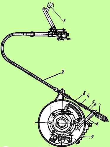
- - set lever 1 (see Fig. 6) to the “released” position, while the rack of lever 5 (see Fig. 5) should be in the forward extreme position (the parking brake warning light should go out);
- - remove the tension spring 9 (see Fig. 3), unscrew remove nut 5, unscrew coupling 4 from rod 6;
- - remove the rubber plug 14 (see Fig. 5) from the caliper 11. Using a screwdriver, catching the tooth on the tooth of the sprocket nut 21, with upward movements, tighten the sprocket nut so that the drum does not turn by hand;
- - unscrew the star nut in the opposite direction so that the brake drum rotates freely without touching the brake pads (check the free rotation of the drum after pressing lever 9 with your hand towards bracket 1 and returning it to its original position);
- - install plug 14 in place;
- - turn lever 9 (see Fig. 5) towards bracket 1, bring the shoe release lever 7 to the stop against the rod 3, without releasing the shoes;
- - screw coupling 4 (see Fig. 6) onto rod 6, ensuring tension in rope 3;
- - lock nut 5;
- - install tension spring 9;
- - remove the car from the jack.
After adjustment, at the maximum stroke of rack 5 (see Fig. 7) of lever 1 (see Fig. 6), the stroke of lever 9 (see Fig. 5) should not exceed 40 mm, and the brake drum in the braked state should not touch the brake pads.
If the brake pad linings are worn out so that the above adjustment does not achieve the effectiveness of the parking brake, it is necessary to remove lever 9 (see Fig. 5) from shaft 18, having first removed the locking ring, rearrange lever 9 on the splines in the direction from bracket 1, install the locking ring and adjust the parking brake.
The design of the brake mechanisms provides for an easily removable brake drum and the ability to visually determine the condition of the brake linings through hatches in the panels.
To replace worn pads, jack up the wheel, remove the tire and, unscrewing the nuts, remove the disc from bolts 16.
Then screw two M16 dismantling bolts 40-60 mm long into the dismantling threaded holes of drum 10 and evenly screw in the bolts to remove the drum.
After this, remove the tension springs, unscrew the bolts 8 and, moving the pads 15 away from the expansion knuckle 14, remove them from the axles 12.
After replacing the worn pads with new ones, install the pads in reverse order. When installing the pads, lubricate axles 12 with Litol-24 grease.
To make it easier to remove the brake drum, as well as when replacing the automatic adjusting lever, to increase the gap between the shoes and the drum, it is possible to unscrew the plug with a 1/8 thread from the lever body, and use a thin screwdriver to remove the movable coupling half 4 from the engagement of the ratchet connection (Fig. 2 ) and turn the worm axis 7 by the hexagon clockwise several turns, then install the plug in place.
After installing the brake drum, it is necessary to adjust the stroke of the brake chamber rod as described above
When replacing only the linings, the pad assembly with the linings must be processed in pairs along the outer diameter to the nominal size, if the drum has not been bored to the repair size.
If the drum was bored to the repair size, then the pads must be machined to the same repair size number.
It is prohibited to install brake pads with linings with different codes (designations) on the side surface of the linings on the same axle and in the brake mechanism.


