Let's consider assembling a diesel engine in a certain sequence, taking into account that our parts and assemblies are previously pre-assembled and tested
For assembly you will need special mandrels and fixtures, which can be made according to the dimensions indicated in the drawings.
Cylinder block subassembly
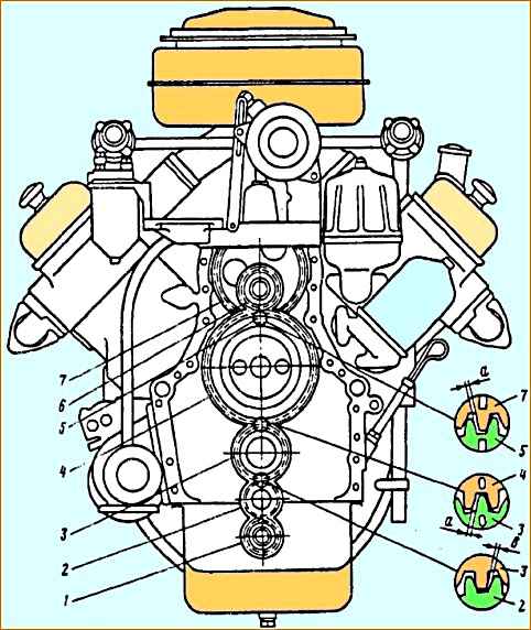
We install the cylinder block on a stand (see picture), securing it with fixing pins for the four holes of the block.
When subassembling the cylinder block, press the alignment pins under the cylinder heads, install the timing gear cover and the flywheel housing.
We press the pins with a mandrel, which ensures that they protrude above the mating planes of the cylinder block by no more than 10 mm.
We clean the oil channels of the block with bristle brushes and a cotton napkin, using a cleaning rod for these purposes.
The plugs of the horizontal and vertical oil channels must be screwed in using nitro putty or thick nitro paint.
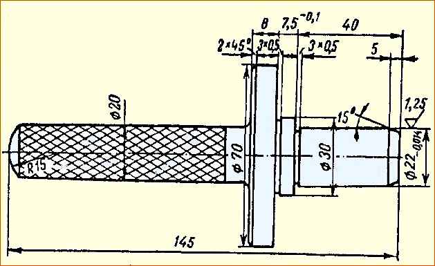
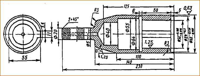
We press the front bushing of the pusher axle into the hole in the block in such a way as to ensure that the hole in the bushing coincides with the oil supply channel in the cylinder block.
The bushing is pressed in with a mandrel (Fig. 1), which ensures a size of 7.5 mm from the front end of the cylinder block to the front end of the bushing.
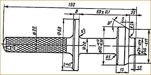
To press in the driven gear shaft seal of the high pressure fuel pump drive:
- - install the oil seal on the mandrel (Fig. 2);
- - Lubricate the outer surface with diesel oil and press it into the bore of the cylinder block, maintaining a size of 69 mm from the front end of the cylinder block to the end of the oil seal (provided by a mandrel).
Installation of the injection pump drive and pushers
We install the injection pump drive into the bore in the upper part of the cylinder block from the front end.
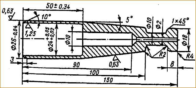
To protect the oil seal from damage, we put a safety mandrel on the free end of the shaft (Fig. 3).
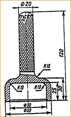
When installing the drive, use a mandrel (Fig. 4) and after installation, the outer rings of the ball bearings should rest against the ledges of the cylinder block sockets.
After aligning the hole in the thrust flange for fastening the drives with the holes in the cylinder block, screw in the bolts with the lock washers on and bend their edges at the edges of the bolt heads, pressing them tightly against the edges.
After tightening the bolts, the fuel pump drive shaft should rotate easily, without jamming.
Then we turn the block 180˚ - the position with the crankcase up and install the pushers.
Pushers are installed on the axle with a gap of 0.012 mm.
Failure to maintain the clearance will cause abnormal engine operation.
With a larger gap, the pushers warp and knock, and with a small gap, they jam.
Pushers installation sequence
Install the extreme axis of the pushers assembly into the front bushing with the plugged end outward, and move the axis inside the cylinder block.
We install sequentially the pushers of the first and fourth cylinders for the YaMZ-236 engine (the first and fifth cylinders for the YaMZ-238 engine) and a spacer sleeve.
Install the remaining pusher axle bushings and the remaining two pushers on the outer axle.
Into the bushing of the third block support cylinders, install the middle axis of the pushers, install the pushers, spacer sleeve and pushers in series.
At the same time, we install pushers for two cylinders on one axis according to the numbering of the cylinders: for YaMZ-238 engines - 2-6, 3-7, 4-8 and for YaMZ-236 engines - 25, 36.
We install the pushers so that the heel of the pusher faces the window in the cylinder block under the pusher rod.
The pushers must rotate on the axles easily, without jamming, and the axial displacement must be limited by spacer bushings. All parts must be wiped and lubricated with diesel oil before installation.
Installing the camshaft and crankshaft
We install the camshaft into the cylinder block complete with gears, having first checked the location of the pushers.
The repair dimensions of the camshaft journals must correspond to the repair dimensions of the holes of the bushings pressed into the cylinder block.
Before installing the camshaft shaft, generously lubricate it with diesel oil and align the installation mark “P” (see Fig. 5) on the tooth of drive gear 5 of the fuel pump drive with the mark “P” on the length of the tooth of driven gear 7 of the injection pump drive.
When aligning the holes of the thrust flange with the holes in the cylinder block, it is necessary to place the flange so that it covers the hole, under the axis of the pushers in the cylinder block.
We screw two bolts with lock washers into the aligned holes. The antennae of the lock washers should fit into the holes of the thrust flange, and the ends of the washers, after tightening the bolts, are bent and pressed against the edges.
After final tightening of the bolts, the camshaft should rotate easily, without jamming.
The circumferential clearance in the gear mesh should be in the range of 0.09 - 0.22 mm; we check the gap at three equally spaced points, with the engine block positioned with the crankcase down.
Install the engine crankshaft. For detailed technology for installing the crankshaft, see the article “Installing the crankshaft on the engine."
Installing the timing gear cover, fan drive, front engine mount bracket and crankshaft pulley.
Before installing the timing gear cover, wipe the mating surface, lubricate it with sealant, and install the right and left cover gaskets.
When installing gaskets, wrinkles, tears, and gaskets should not overlap the connecting channels.
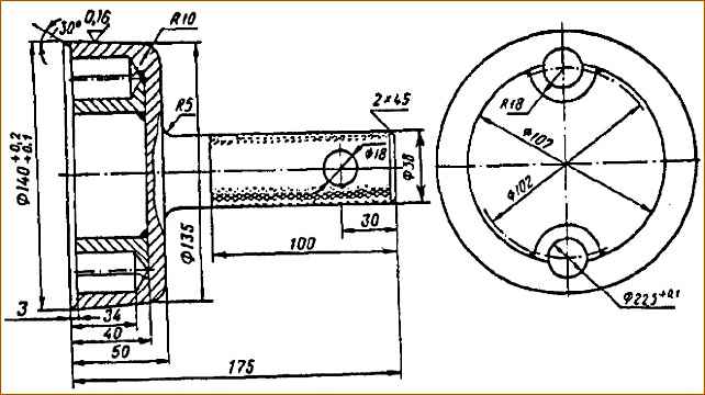
To protect the crankshaft oil seal in the cover from damage, put a safety mandrel on the front end of the crankshaft (Fig. 6) and lubricate the oil seal with diesel oil.
We install the timing gear cover on the pins of the cylinder block, having previously wiped the mating surfaces, and secure it with ten bolts with flat and spring washers.
We install the fan drive on the studs of the timing gear cover, having previously installed the gasket. In this case, the fan drive gear must engage with the camshaft gear.
We secure the fan drive with four nuts and washers.
We install the top cover of the cylinder block on the studs and secure it with two bolts and five nuts with flat and spring washers.
Before installing the cover, it is necessary to wipe the mating surface and install a gasket on the studs. When attaching the cover, do not completely tighten the bolt and nut under the generator bracket.
Then we install the hatch plug gasket and the plug itself on the top cover, which we fasten with four bolts with attached spring washers.
We install the front engine mount bracket on the timing gear cover and secure it with four bolts with attached spring washers.
The bolts must be tightened to a torque of 90-110 Nm (9-11 kgcm). Before installing the front support, you must wipe the mating surfaces.
When installing the crankshaft pulley, it is necessary to rotate the crankshaft to the locking position scoop the segment key and press it into the keyway of the front end of the crankshaft.
Then we wipe the seating surfaces and press the pulley onto the front end of the crankshaft until it stops against the collar and secure it with a bolt and a washer.
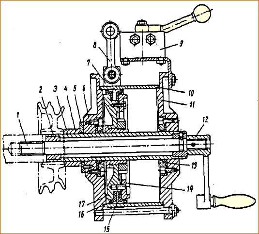
When pressing the pulley onto the front end of the crankshaft, use a pneumatic device (Fig. 7).
To do this, install a pulley on pipe 3, use handle 12 to screw rod 1 into the hole in the crankshaft under the pulley mounting bolt.
Align the groove in the pulley with the key at the front end of the crankshaft and supply air to cylinder 10 by opening valve 9.
When the piston moves along with pipe 3 and bushing 4, the pulley is pressed on.
For ease of operation, we hang the device on the balancer by the earring 8.
The air pressure in the system must be maintained within 0.5-0.6 MPa (5-6 kgf/cm 2).
Installing the flywheel housing, flywheel and vent tube.
To install the flywheel housing, it is necessary to turn the cylinder block 90° with the rear end up, wipe and lubricate the mating surface of the cylinder block under the flywheel housing with sealant.
Then we install the flywheel housing gasket on the locating pins on the cylinder block and the safety mandrel (Fig. 8) on the rear end of the crankshaft.
The surface of the mandrel and the working edge of the oil seal must be lubricated with diesel oil.
We install the flywheel housing on the locating pins of the cylinder block and fasten it with bolts with attached spring washers, which we tighten with a torque of 80-100 Nm (8-10 kgf m).
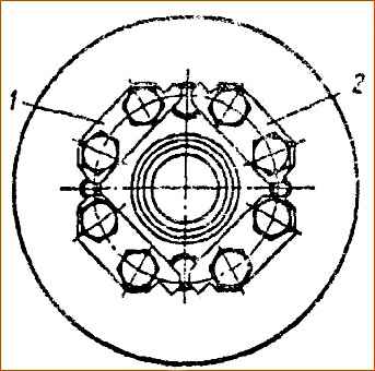
We install the flywheel on the crankshaft dowel pins using a suspension.
Tighten the flywheel mounting bolts to a torque of 200-220 Nm (20-22 kgf m) and lock them with locking plates installed under the head of each pair of bolts, and bend them at the edge of the bolts, as shown in Figure 9.
To facilitate installation of the flywheel in the correct position relative to the crankshaft, the numbers 2 are stamped on the flywheel hub and on the end of the shaft, which must be aligned during assembly.
We attach the ventilation tube to the cylinder block with two bolts with engraving washers.
To do this, insert bolts with washers into the holes of the ventilation tube, put a gasket on the bolts and install them on the cylinder block, screwing the bolts in 1-2 threads by hand, then install a clamp on the ventilation tube and secure it with a bolt to the flywheel housing.
After this, finally tighten the bolts securing the ventilation pipe.
Installation of CMO filters and fuel injection pump
When installing centrifugal and coarse oil filters, the surfaces of the cylinder block must be wiped, lubricated with sealant and gaskets applied.
We install the high-pressure fuel pump on the platforms located between the cylinder cambers and turn the crankshaft to the position for pressing the key into the driven gear shaft of the fuel pump.
To protect the shaft, install a stand under it and press the key in with a mandrel.
Then we install the half-coupling assembly on the shaft of the driven gear of the injection pump drive. Before installation, you need to check the alignment of the marks marked “O” on the flange and coupling half.
We install the fuel injection pump assembly with the speed regulator and the automatic injection advance clutch on the block and fasten it with four bolts, having previously put washers on them.
We connect the automatic injection advance clutch of the injection pump to the half-coupling of the driven gear shaft using a textolite washer.
In this case, it is necessary to ensure the axial clearance between one cam of the driving half-clutch and the end of the automatic injection advance clutch within 0.5-0.6 mm, and the clearance between the second cam and the end of the clutch is at least 0.5 mm.
We check the gaps with a set of feeler gauges.
In addition, it is necessary to ensure that the marks on the drive half-clutch and the automatic injection advance clutch match, fasten the nut of the driven gear shaft coupling half and secure it with a cotter pin.
We will consider the continuation of diesel assembly in the following articles, which will cover:
- - cylinder-piston group assembly technology;
- - installation of the oil pump;
- - installation of cylinder heads, valve rocker arms and adjustment of valve clearances;
- - installation of injectors, fuel lines and connecting pipe;
- - engine running-in and testing;
- - cold running-in of the engine;
- - hot engine run-in.
")

")
")
")
")
")
")
")