Removing the electronic control unit (ECU)
Disconnect the intermediate harness (1) (650.3724014), engine sensor harness (2) (650.3724012) and injector harness (3) (650.3724010) from the electronic control unit.
Remove the engine sensor harness and injector harness mounting brackets by unscrewing the screws (7) and remove the intermediate harness clamp by unscrewing the nut (9).
Remove the fuel pump tube (4) (650.1104416).
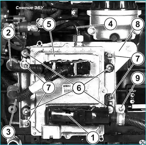
Remove the ECU (5) (650.3763010) by unscrewing the nuts (6).
Remove the ECU spacer (8) (650.37631 06) by unscrewing the three bolts securing it.
Removing the engine harnesses
Disconnect the sensor harness from the oil pressure sensor and the crankshaft speed sensor.
Remove the harness fastening clamps.
Remove the injector harness (650.3724010), engine sensor harness (650.3724012) and intermediate harness (650.3724014).
Installing the engine harnesses:
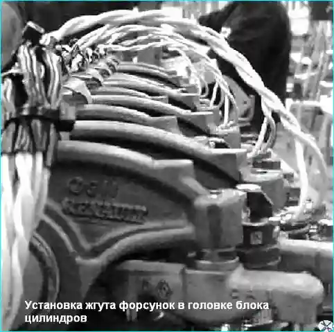
Route the injector harness along the engine.
Install the L-shaped adapter in the head hole.
Install the L-adapter mounting bolt and tighten it finally to a torque of Мкр = 20 ± 4 Nm.
Connect the injector harness to the injectors.
Tighten the nuts securing the wires to the injectors and tighten it finally to a torque of Мкр = 1.5 ± 0.25 Nm. (Fasten the wires so that the wires from the injectors go in the direction opposite to the rocker arm axis) (see Fig. 2).
Route the sensor harness along the engine.
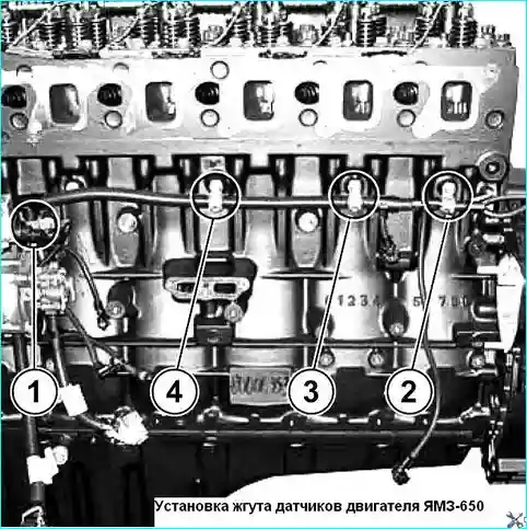
Secure the harness at point (1) (see Fig. 3), installing a clamp between the harness branch tee and the branch tee to the pressure sensor in the rail.
Then sequentially secure the harness at points (2, 3, 4) (see Fig. 123).
Tighten clamp fastening bolts with a torque of Mkr = 20 ± 4 Nm.
Route the intermediate harness along the engine.
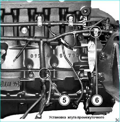
Fasten the harness at point (5) (see Fig. 4), installing the clamp between the branch tee to the water level sensor in the fuel and the branch tee to the fuel filter heating relay.
Fasten the harness at point (6) (see Fig. 4), installing the clamp.
Tighten the clamp fastening bolts with a torque of Mkr = 20 ± 4 Nm.
Installing the electronic control unit
Install the ECU spacer on the unit, screw in the mounting bolts (1) M8x1.25-20 and (2) M8x1 25-25, tighten to a torque of Мкр = 20 ± 4 Nm (see Fig. 5).
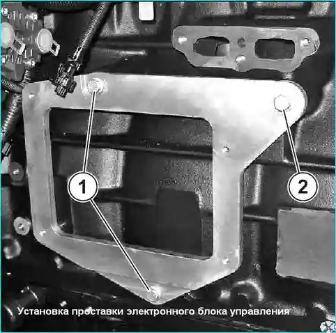
Install the bracket mounting screw and tighten to a torque of Мкр = 7.5 ± 1.5 Nm.
Install the electronic control unit assembly on the spacer studs, screw on the mounting nuts and tighten torque Мкр = 10 ± 2 Nm.
Install the angular connectors of the electrical wiring harnesses into the connectors of the electronic control unit (do not touch the connector contacts).
Fasten the electrical wiring harnesses to the brackets using clamps, screw the nuts of their fastening onto the studs of the brackets and tighten with a torque of Мкр = 7.5 ± 1.5 Nm.
Install the fuel injection pump tube.
Tighten the union nuts with a torque of Мкр = 28 ± 2 Nm.
Connect the sensor harness to the engine sensors.


