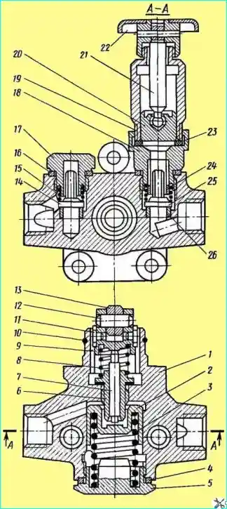
Fuel pump (Fig. 1). Piston type, mounted on the high-pressure fuel pump and driven by the camshaft eccentric
Piston 2, piston spring 3, resting with one end against the piston, the other against the plug 5, suction 25 and discharge 14 valves, which are pressed against seats 26 by springs 15, are placed in the pump housing 1.
The cavity of the pump housing in which the piston moves is connected by channels with cavities above the suction and below the discharge valves.

Fig. 1. Fuel booster pump: 1 - housing; 2 - piston; 3 - piston spring; 4 - sealing washer; 5 - plug; 6 - rod bushing; 7 - pusher rod; 8 - pusher spring; 9 - piston pusher, 10 - retaining ring; 11 - pusher cracker; 12 - roller axis; 13 - treader roller; 14 - discharge valve; 15 - spring; 16 - sealing washer; 17 - plug; 18 - hand pump cylinder housing; 19 - hand pump cylinder; 20 - hand pump piston; 21 - piston rod; 22 - handle; 23 - gasket; 24 - cylinder housing bushing; 25 - suction valve; 26 - valve seat
The piston is driven by the pusher 9 through the rod 7.
The roller 13 of the pusher rotates on the floating axis 12, locked from longitudinal movement by two crackers 11.
At the same time, the crackers, moving in the grooves of the housing 1, prevent the pusher from turning.
The spring 8, resting against the sleeve 6, presses the pusher against the eccentric.
The rod 7 moves in the guide sleeve 6, which is wrapped with special glue in the pump housing. The rod and bushing are a precision pair.
A hand priming pump is installed on the fuel priming pump.
A rubber gasket 23 serves as a seal between the body 18 of the pump cylinder and the cylinder 19, which, when the handle 22 is screwed onto the cylinder, simultaneously seals the gap between the piston 20 and the body 18.
Repairing the fuel priming pump
The fuel priming pump (see Fig. 1) is disassembled in the following sequence:
- - unscrew the hand pump assembly and the valve plug;
- - remove the valves and their springs;
- - unscrew the spring plug and remove the piston spring and piston;
- - remove the retaining ring, remove the pusher and the spring pusher.
When disassembling and assembling the fuel pump, remember that the piston and body of the booster pump, as well as the piston and cylinder of the hand pump are precisely matched pairs and cannot be disassembled.
Mechanical failure of parts and thread stripping are not allowed.
The body of the fuel pump must not have breaks, cracks or damage to the threads for the bolts securing the fuel lines.
The permissible gap between the body and the piston of the pump must not exceed 0.18 mm.
The gap in the connection between the pump body and the pusher must not exceed 0.2 mm.
The piston of the fuel pump must not have wear from the pusher rod with a depth of more than 0.25 mm.
The pump valve with the end surface of the seat must ensure tightness connections.
When assessing the condition of the remaining parts, remember that the gap should not exceed:
- - between the roller axis and the piston pusher 0.15 mm;
- - between the pusher roller and the roller axis 0.28 mm;
- - between the cylinder and the piston of the hand pump 0.05 mm.
Special attention should be paid to the condition of the rod-sleeve assembly. The gap in the specified connection should not exceed 0.014 mm.
The density of the specified pair is checked by the time of pressure drop from 150-120 kgf/cm² as a result of fuel flowing through the gap between the bushing and the rod.
Tests should be carried out on filtered summer diesel fuel or on its mixtures with aviation or spindle oil or tractor kerosene.
The viscosity of the mixture at a temperature of 20˚C should be 1.4 -1.5 conventional degrees. The time for the pressure to drop to the specified limits must be at least 1 min.
If the density is lower, replace the pair.
Assemble the fuel pump in the reverse order of disassembly.
If the precision rod-bushing pair unit is replaced, the thread surface and the end face in the pump body must be thoroughly cleaned of any remaining adhesive on which the removed rod bushing was installed.
The new bushing must be installed in the pump body using epoxy-based adhesive.
To ensure the strength and tightness of the connection using adhesive, the thoroughly cleaned contact surfaces of the pump body and rod bushing must first be degreased with gasoline or another liquid.
Tighten the rod bushing with a torque of 1 kgf/cm.
After tightening, check the ease of movement of the rod along the in the sleeve.
If the movement of what if it is difficult, you need to slightly loosen the sleeve.


