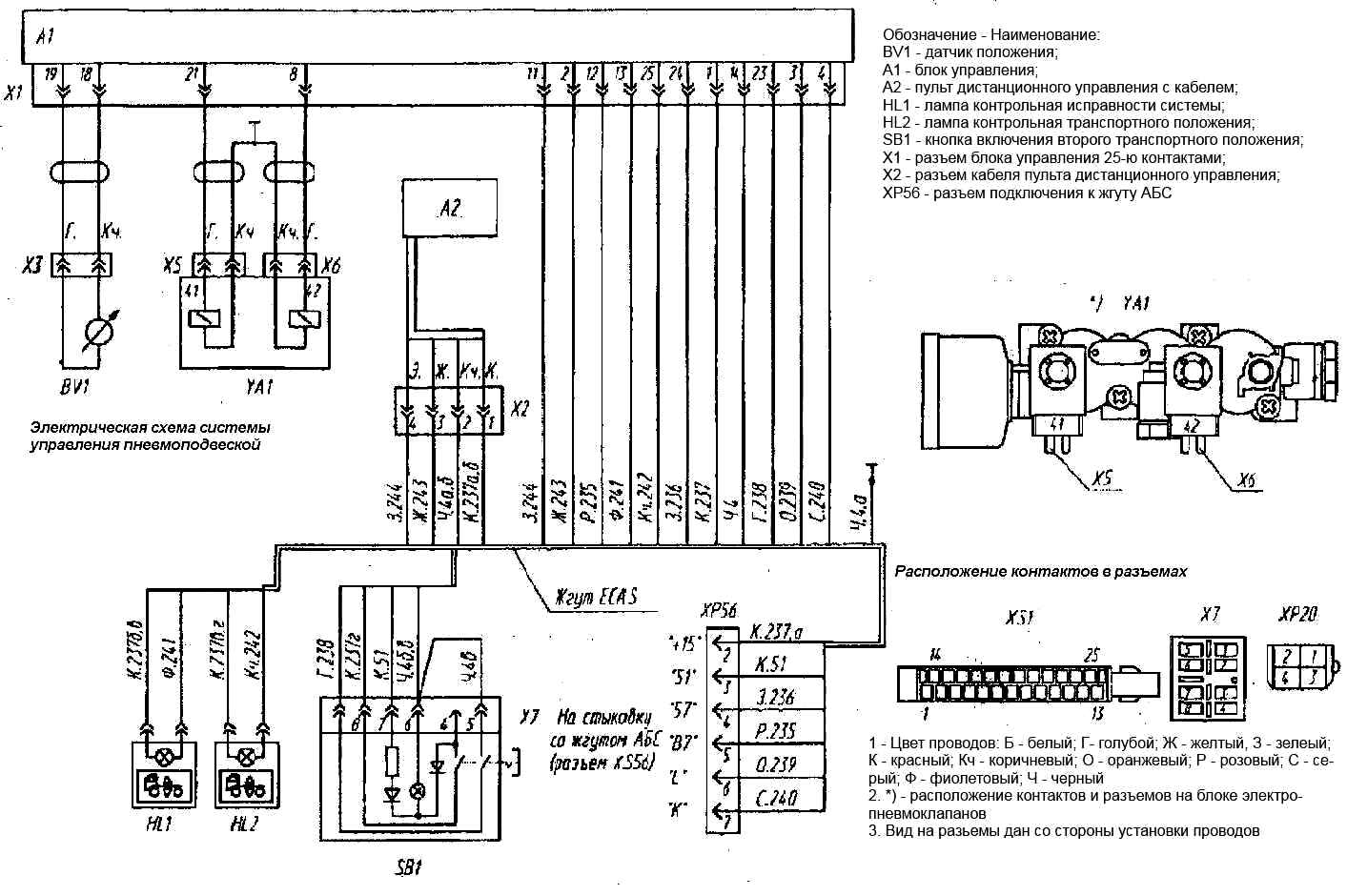
When vehicles are equipped with air suspension, an electronic control system of the ECAS type (by Wabco) is installed
The system contains a microprocessor unit 18 (figure) located under the instrument panel, a suspension remote control 19 installed on the left side of the driver's seat, a block of electro-pneumatic valves 17 and an inductive suspension position sensor 16 installed in the rear of the right frame side member.
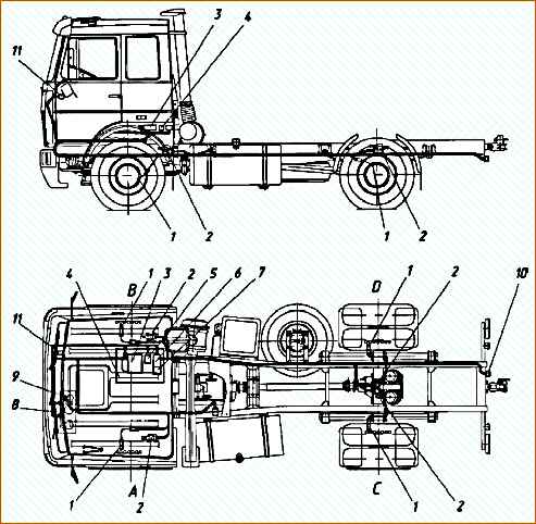
Indicator lamps 8 and 9 (Figure 2) with suspension control symbols are installed on the main instrument panel, switch 10 of the second transport position is on the additional instrument panel on the right side of the driver.
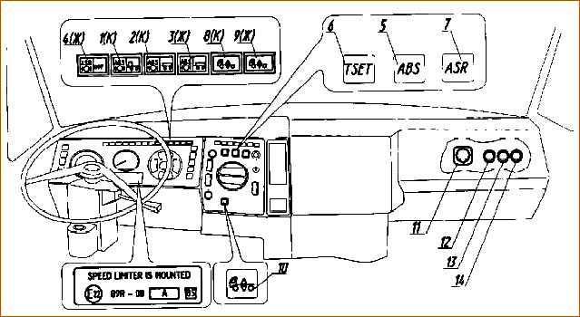
The system also has diagnostic lines connected to diagnostic connector 11.
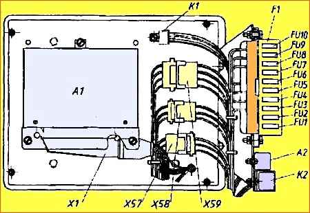
Fuses FU6, FU7 of the suspension control system are installed in the fuse box (Figure 3), which is located on the connection board of the ABS electronic units.
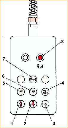
The location of the buttons on the remote control is shown in Fig. 2
System functions:
1. When the starter switch is turned to the “instruments” position, it conducts preliminary diagnostics of all its devices and warning lamps. In this case, both indicator lamps 8 and 9 (Fig. 6) light up and go out after 2-3 s, if the control unit has not detected any errors.
Then, if there is sufficient pressure in the reservoir and the hand brake is released, the system automatically sets the suspension to the position in which it was when the power was previously turned off.
2. Allows you to adjust the height of the saddle (platform), as well as remember any two height positions and, if necessary, set any of them using the remote control.
Note. Regulation from the remote control is carried out while the vehicle is stationary or at a speed below 30 km/h.
3. Automatically maintains the previously set height and locks the suspension when braking.
At a speed of more than 30 km/h, the height is automatically set to the “transport” position, at a speed of more than 60 km/h - the second “transport” position (to reduce the height of the center of gravity and increase the stability of the vehicle).
The system also allows you to set the first or second “transport” height position using switch 10 (Fig. 6).
4. Provides built-in self-diagnosis while driving and, if a malfunction or error is detected, signals this to the driver by turning on the red warning lamp.
The remote control is turned on and off with button 7 (Fig. 6), and, accordingly, lamp 8 on the remote control should light up or go out.
Control from the remote control is as follows:
- - raising/lowering by pressing buttons 1, 2 (Fig. 4);
- - setting the height to the “transport” position when pressing button 4;
- - the set level is recorded in memory by pressing button 3 (“STOP”) and not releasing it - pressing button 5 or 6 (“memory” M1 or M2);
- - setting the height level previously recorded in memory by pressing button 5 or 6 (“memory” M1 or M2);
- - interrupt the process of changing the height level
- - when you press button 3 (“STOP”).
Red indicator lamp 8 (Fig. 6) signals the serviceability/malfunction of the system, and also serves as a means of displaying information about the type of malfunction during diagnostics.
The yellow indicator lamp 9 signals the state of the “transport” position of the suspension and can go out if the height level is set to the specified position, or remain on if the height level is different from the specified one.
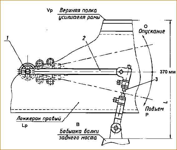
When setting the height to the “transport” position, sensor 16 (Fig. 1) must be in the position shown in Fig. 6.
Installation of lever 2 in a horizontal position with the “transport” position set (370 mm) is carried out by adjusting the length of rod 3.
The system does not require special maintenance, except for a functional check
System verification
1. Before checking the operation, make sure that there are no compressed air leaks from the pneumatic system.
Enable the "mass" button.
Turn the starter and instrument switch to the “instrument” position. In this case, they should light up at the same time and after 2 seconds. turn off all warning lights of the air suspension system (Fig. 5).
- 2. Start the engine and increase the pressure in the air suspension receivers to normal (6.9-8.2 kgf/cm 2).
- 3. If the yellow transport position control lamp is on on the instrument panel, this indicates that the vehicle’s suspension is in a position other than transport, and it is necessary to set it to transport position by pressing button 4 on the remote control (Fig. 4).
When the transport position is established, the warning light should go out. It is necessary to ensure that the air suspension system has established the nominal height (transport position) of the cargo platform (see Fig. 5).
- 4. Change the platform level using the “up” and “down” buttons, and the yellow indicator lamp for the “transport” position should light up.
- 5. Write any two platform height settings into the memory of the electronic unit.
For this must be set to the desired position using the “up” or “down” buttons on the control panel, press the “STOP” button and any of the “M 1” (memory 1) or “M2” (memory 2) buttons without releasing the “STOP” button (Fig. 4).
- 6. Move the suspension to the “transport” position by pressing the corresponding button and check whether the system sets the platform height previously recorded in “memory” or not when you press the “M1” and “M2” buttons on the remote control.
At the same time, when the height of the platform approaches the level set or previously recorded in the “memory”, the characteristic noise of switching valves will be heard (you can stop the regulation by pressing the “STOP” button).
After this, check whether the “transport” position of the suspension is automatically set when starting to move (at speeds above 30 km/h, the “transport” position is automatically set and the yellow warning lamp on the instrument panel should go out).
Possible malfunctions in the suspension control system and ways to eliminate them
Fault
Reason
- Remedy
When the starter lock key is turned to the “Instruments” position, the warning lamp does not light up
- The vehicle’s on-board voltage is missing or low, the battery is discharged
- Check the on-board voltage, fuses, charge the battery
- There is no supply voltage to the control unit (CU)
- Check the CU power fuses and wiring.
- Fix the wiring fault and replace the fuses
When the starter lock key is turned to the “Instruments” position, one of the indicator lamps does not light up
- faulty warning lamp or wiring
- Replace the warning lamp, eliminate the wiring fault
- Control unit malfunction
- Replace the control unit
After turning the key to the “Device” position, the red indicator light does not go out
- Sensor coil malfunction, poor contact in the connector connecting the sensor to the cable, cable break
- Check the active resistance of sensors and cables, determine where the fault is.
- Fix the problem by replacing the sensor or cable.
- Faulty solenoid valve coils, broken contact in the connector, faulty connecting cable
- Check the active resistance of the solenoid valve coils, cable and connector.
- Loss of contact in the switching block of the block or the circuit of terminal B7 of the tachograph
- Determine where the problem is.
- Fix the problem by replacing the modulator or cable
- Restore contact in the tachograph block or circuit
- Control unit malfunction
- Replace the control unit
After turning the key to the “Device” position or when driving, the yellow indicator light comes on and does not go out
- Lack or insufficient pressure of compressed air in the receiver
- Start the engine and bring the pressure in the receivers to normal (6.9-8.2 kg/cm 2)
- The fastening or installation of the sensor or sensor lever is broken
- Check the sensor fastening and the installation of the sensor lever.
- The sealing of the air cylinder or pipelines is broken
- Fix the problem
- Check the system for leaks.
- Fix the problem
When driving, the red warning lamp lights up or flashes
- Broken contacts, short circuit or broken sensor cables or electromagnetic cables
- Check the wiring, electrical connections and active resistance of the sensor and solenoid valves.
- Replace faulty products
When you press the remote control buttons, there are no reactions from the suspension
- System power is not connected, fuse is faulty
- Check the power circuit, replace the fuse
- Check connection.
- The remote control is not connected or not turned on
- Connect or turn on the remote control