Cars can be equipped with a 4-channel anti-lock braking system (ABS) of type 4S/4M (4 sensors/4 modulators) with a microprocessor control unit. Wabco (Germany) or BPO "Ekran" (Belarus)
The main purpose of the system is to automatically maintain optimal braking of the vehicle without blocking (skidding) the wheels, regardless of what road braking occurs on - slippery or dry.
Thanks to this, cars acquire a number of advantages:
- - increasing active safety by ensuring stability and controllability during braking and increasing the braking efficiency of the vehicle, especially on wet and slippery roads;
- - extending the service life of tires;
- - the ability to increase the average safe speed.
In addition, the applied ABS design f. Wabco can provide a speed limit mode, and the ABS BPO "EKRAN" provides storage and display of information about the effectiveness (average deceleration) of the vehicle's last braking and pre-crash operating modes of the system for the last 40 seconds.
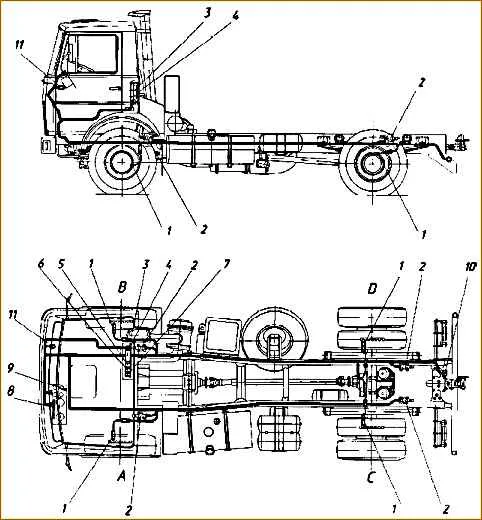
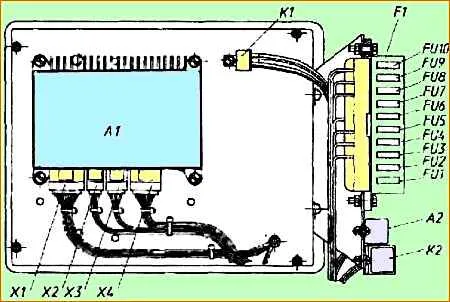
Arrangement of ABS elements on a 2-axle vehicle with a small cabin: 1 - wheel speed sensors; 2 - electric pneumatic brake pressure modulators; 3 - microprocessor control unit; 4 - circuit board; 5 - switching relays; 6 - fuse block; 7 - info module; 8 - control lamps; 9 - ABS operating mode switch; 10 - trailer ABS power socket; 11 - diagnostic connector
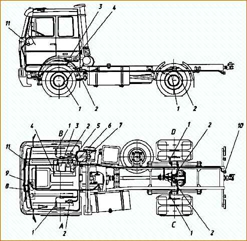
Arrangement of ABS elements on a 2-axle vehicle with a large cabin: 1 - wheel speed sensors; 2 - electric pneumatic brake pressure modulators; 3 - microprocessor control unit; 4 - mounting board; 5 - switching relays; 6 - fuse block; 7 - info module; 8 - control lamps; 9 - ABS operating mode switch; 10 - trailer ABS power socket; 11 - diagnostic connector
The location of the system elements on the car chassis is shown in Fig. 1.
The system contains inductive wheel speed sensors 1, electro-pneumatic brake pressure modulators 2 installed in the brake lines in front of the brake chambers of the rear and front wheels, an electronic unit 3 mounted on a switching board 4 installed under the berth behind the passenger seat, relay 5 and fuse block 6.
Diagnostic connector 11 and buttons 12 and 13 for calling the ABS diagnostic mode of the tractor and trailer are located under the right cover of the instrument panel (Fig. 2).
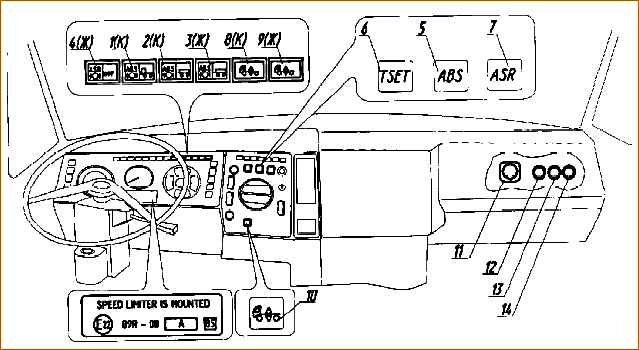
Location of warning lamps and ABS elements on the instrument panel: 1 - tractor ABS warning lamp; 2 - trailer ABS warning lamp; 3 - warning lamp for the ABS trailer power supply circuit; 4 - indicator lamp for ABS mode and ABS/ABS diagnostics; 5 - ABS operating mode switch; 6 - “TEMPOSET” mode switch (only for vehicles equipped with a speed limiting device); 7 - PBS mode switch (only for cars with installed PBS); 11 - diagnostic connector ISO 9141; 12 - vehicle ABS diagnostic button; 13 - trailer ABS diagnostic button
Indicator lamps 1, 2, 3 and 4 and switches 5, 6 of ABS operating modes are installed on the main and additional instrument panel (Fig. 3).
Indicator lamps 1 and 2 (red) with the ABS symbol indicate the serviceability/malfunction of the ABS of the tractor or trailer, lamp 4 (ASR/INF) - serves as a means of displaying information about wheel slip, as well as the type and location of the malfunction in the system diagnostic mode.
When installing ABS BPO “Screen” on the specified lamp, information about braking efficiency is also provided.
Switch 5 is designed to switch the ABS to a special operating mode when braking the car in mountainous areas (for example, when descending a mountain) on a road covered with gravel or loose snow.
Switch 6 is used when enabling Temposet mode (speed limit).
On the rear beam of the cab support there is a socket for connecting the trailer ABS power cable and a parking socket (Fig. 1).
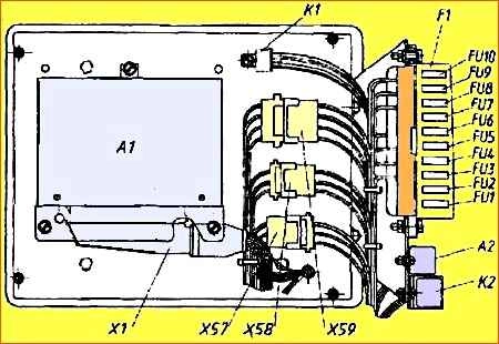
The location of ABS elements and electronic units on the switching board is shown in Fig. 4 and 5
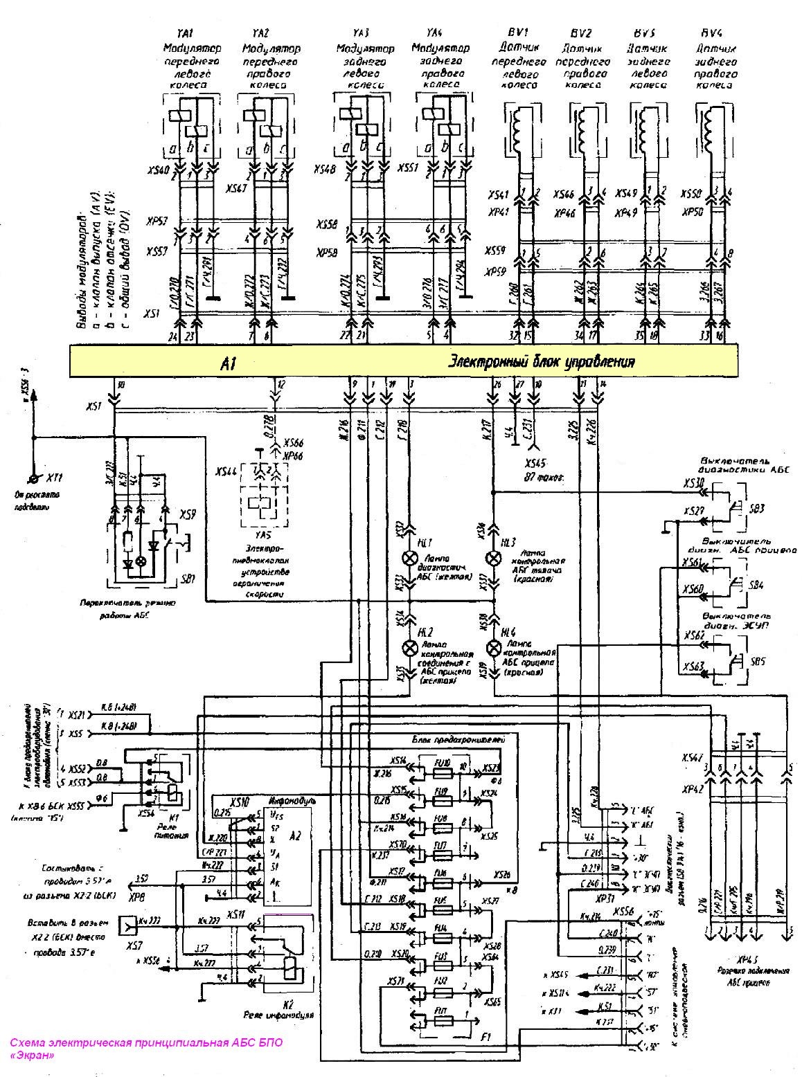
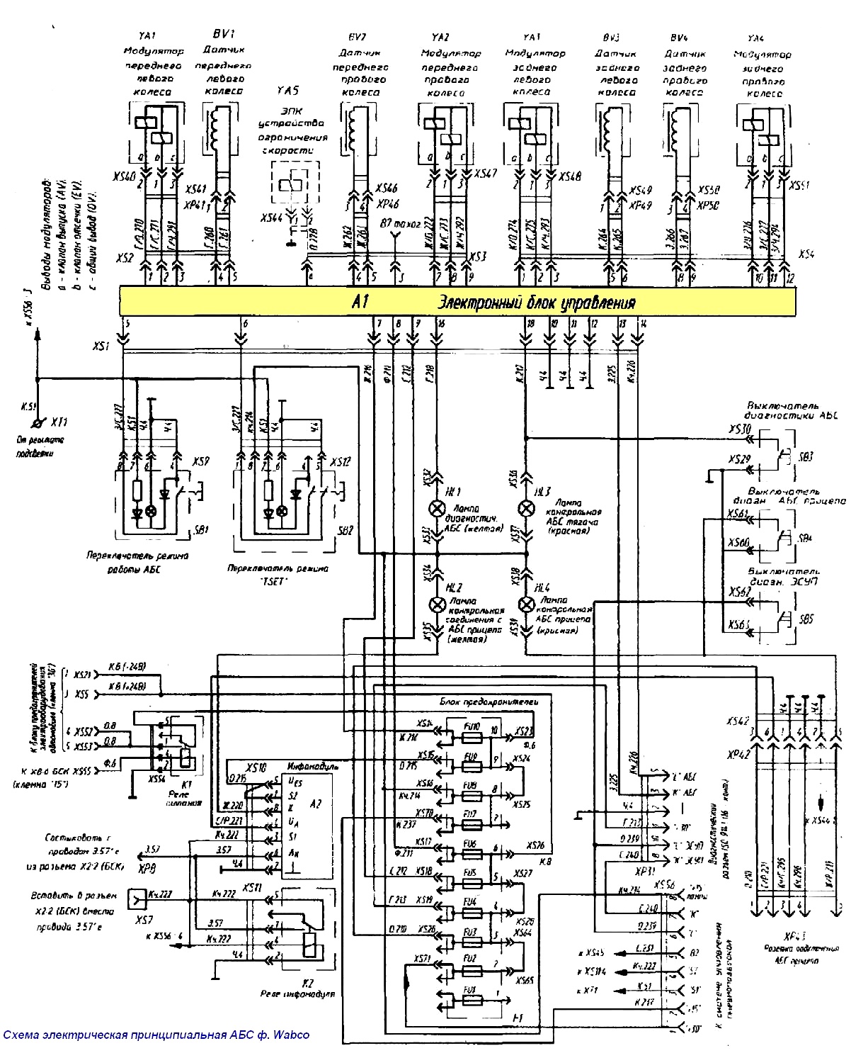
Electrical connection diagram of ABS elements BPO "Ekran" and ABS f. Wabco is shown accordingly in Fig. 6 and 7.
System operation
When the power is turned on (when the starter lock key is turned to the “instruments” position), the indicator lamps with the ABS ASR/INF symbol (Fig. 2) turn on and test control of the electronic unit and electrical circuits of sensors, modulators and switching devices takes place.
If the system is working properly, the ASR/INF lamp goes out 2-3 seconds after turning on the power, and the lamp with the tractor ABS symbol goes out when starting to move, when the vehicle reaches a speed of 5-7 km/h.
If a malfunction occurs in the system or electrical circuits of one of the elements (sensors, modulators, etc.) or control circuits, the red indicator lamp with the ABS symbol lights up.
In this case, the power to the corresponding circuits (modulators) is turned off and the brake system or the unregulated ABS circuit of the brake system operates as usual (from the brake valve),
The system does not require special maintenance, except for checking the operation and checking the installation of ABS sensors when adjusting or replacing bearings in wheel units or changing brake linings (if the hubs were removed).
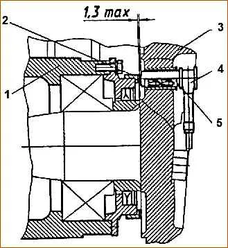
1 – wheel hub; 2 – rotor; 3 – steering knuckle; 4 – sensor stator; 5 – clamping sleeve
For normal ABS operation, the gap (see Fig. 7 and 8) between the stator and the rotor of the sensor should not exceed 1.3 mm.
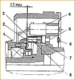
1 – wheel hub; 2 – rotor; 3 – sensor bracket; 4 – brake caliper; 5 – hole in the caliper; 6 – plug; 7 – sensor stator; 8 – clamping sleeve
For normal operation of ABS, the gap between the stator and rotor of the sensor should not exceed 1.3 mm
To set the minimum working gap between the stator and the rotor, it is necessary to apply the sensor stator to its end with a force of 120-140 N (12 - 44 kgf) or by lightly tapping with a non-metallic object (in the wheel assembly of the rear axle through a special hole in the caliper and a plug in the brake shield), move it in the clamping sleeve in the axial direction until it stops at the rotor crown, and turn the wheel hub 2-3 turns.
If the red lamp with the ABS symbol does not go out at a speed above 7-10 km/h, you should check the installation of sensors in the wheel assemblies, diagnose the system using light flashing codes, repeat the control check of the system with an analysis of possible faults using the table, or contact to a service station to troubleshoot the problem.
System verification
The control check consists of three stages: preliminary check, check of operating modes and check of the diagnostic mode.
1. Preliminary check
- 1.1. By external inspection, verify the reliability of the connection of cable devices, connectors of the electronic control unit, modulators, sensors, as well as relays and fuses and ABS warning lamps.
- 1.2. Turn on the remote ground switch button. Turn the starter switch to the “instrument” position. In this case, the indicator lamps with the ABS and ASR/INF symbols light up and should light up briefly (determined by ear) modulator valves.
If the electrical part of the system is working properly, the ASR/INF indicator lamp should go out after 2-3 seconds.
- 1.3. Start the engine and bring the pressure in the circuits to normal (6.9-8.2 kg/cm2). Press the brake pedal. In this case, the brake mechanisms must operate, and there must be no air leaks from the system.
- 1.4. Start moving. At speeds above 7 km/h, the red warning light with the tractor ABS symbol should go out (if the vehicle is coupled to a trailer, the warning light with the trailer ABS symbol should also go out).
2. Checking ABS operating modes
2.1. Main mode
Checking the main operating mode of the ABS is carried out with switch 5 (Fig. 2) in its initial (not pressed) state. In this case, it is necessary to accelerate the car to a speed of 35-45 km/h and apply sharp braking on surfaces with a high (asphalt) and low coefficient of adhesion (wet asphalt concrete, snow, ice).
The wheels should not be blocked (only short-term blocking is allowed at speeds below 15 km/h), the car should slow down with the prescribed efficiency (on dry asphalt i = 5 m/s2) and the characteristic sound of the brake pressure modulators should be heard in the mode of cyclic release of compressed air from the brake chambers.
Indicator lamp 1 with the ABS symbol should light up when the starter switch is turned back to the “instrument” position.
Checking special mode
Checking the special operating mode of the ABS is carried out in the same way when switch 5 is on (pressed) (Fig. 2).
In this case, the red indicator lamp 1 should operate in a flashing mode, and the ABS system in a lower frequency mode.
Checking the “Temposet” speed limit mode.
The mode is activated when the vehicle speed is at least 25 km/h. To do this, when the set speed is reached, press switch 6 (Fig. 2) with the “TSET” symbol. In this case, the lamp with the ASR/INF symbol should light up.
At a driving speed lower than the speed at which the Temposet mode was activated, the ASR/INF lamp does not light up.
Checking the diagnostic mode
Checking the system operation in diagnostic mode is carried out in three stages:
- 3.1. When turning the starter switch from the off state to the “instrument” position. In this case, the red control lamp with the ABS symbol lights up, and the electromagnetic pilot valves of the modulators should operate (briefly) (determined by ear).
- 3.2. When starting to move. When the vehicle speed is above 7-10 km/h, the red warning lamp with the ABS symbol should go out.
- 3.3. When you press the diagnostic button 12 (Fig. 2), the lamp with the ASR/INF symbol should display a light flashing code, as described below.
Attention:
- 1. The special ABS operating mode is activated only during testing or driving in mountainous areas. After which the specified mode (switch 3) should be turned off.
- 2. When carrying out repairs and troubleshooting, it is necessary to turn off the engine and turn off the power to the system.
The system power is turned off when the starter and instrument switch key is turned to the “off” position and the ground switch is turned off.
To temporarily disable the ABS, for example, when checking the simultaneous operation of the wheel brakes and the effectiveness of skid braking, remove fuse FU10 from the socket in the fuse block (Fig. 3, 4).
3. It is strictly forbidden to carry out welding work on a vehicle with the electronic unit installed. In this case, the electronic unit must be disconnected and removed from the vehicle.
If difficulties arise in determining the malfunction, the fuses are checked (Fig. 3 and 4), control diagnostics of the system using flashing light codes, or a comprehensive check with a special diagnostic tester.
Possible malfunctions of the ABS system and solutions
Symptoms of malfunction
- Possible reason
Remedy
When you turn the ignition key, the “instruments” indicator lamps with the symbols “ABS” or “ASR/INF” do not light up
- There is no or low voltage in the vehicle network, there is no voltage in the control unit
Check the mains voltage. Check the ABS/ASR power fuses
- Malfunction of indicator lamps or wiring
Replace the faulty lamp, check the wiring
- Control unit malfunction
Replace the control unit
When the ignition key is turned to the “instruments” position, the “ABS” and “ASR/INF” indicator lamps light up and do not go out
- Open circuit or short circuit in the cable circuits or connectors of sensors, modulators or PBS electropneumatic valves
Check the circuits of sensors, modulators and electro-pneumatic valves of the PBS with a tester, eliminate the malfunction
When driving at a speed of more than 7 km/h, a red warning lamp with the symbol “ABS" of the tractor or trailer does not go out
- The gap between the sensor stator and the rotor has been increased
Check the voltage of the output signal of the sensors with a tester, adjust the gap
- Malfunction of the sensor coil, broken contact in the connector connecting the sensor to the cable, cable break
Check the active resistance of sensors and cables, restore contact, replace the sensor.
- Malfunction of the coil of the modulator solenoid valves, broken contact in the connector, faulty cable
Check the condition of the coils, cable and connector.
- Lost contact in switching blocks
Restore contact
- Wiring fault or control unit fault
Check relay and wiring. Replace faulty elements.
After reaching a speed of 5-7 km/h, the indicator lamp with the “ABS” symbol goes out and starts flashing at a frequency of 0.5 Hz
- The ABS operating mode switch is in the “closed” state or the switch contact is closed to ground
Check switch.
Remove short circuit.
When braking, the red warning lamp with the “ABS” symbol lights up, the ABS operates intermittently
- Lost contact in the switching board block, the control unit is not fastened
Restore contact, secure the control unit
- The fastening of one of the wheel sensors is broken or the air gap is increased
Check the sensors, restore the air gap
When braking, the ABS is activated, but one of the wheels is blocked
- Lubrication failure and jamming of the expansion fist or brake pad rollers
Disassemble the wheel assembly, eliminate the malfunction, restore lubrication.
- The tension spring of the brake pads is weakened or broken
Replace the spring
- Incorrect connection of sensors and modulators
Check the connections of sensors and modulators for compliance
When the brake pedal is pressed, air is released from the atmospheric outlet of the modulator
- The sealing of the outlet diaphragm valve of the modulator is broken due to a foreign body getting between the valve seat and the diaphragm
Replace or disassemble the modulator and eliminate the malfunction, followed by checking its tightness.
When you press the brake pedal, the yellow lamp with the trailer “ABS” symbol lights up
- The connection in the trailer ABS power connector is broken, the trailer ABS power cable is not connected or broken, the trailer ABS electronic unit is faulty or missing (the trailer is not equipped with ABS)
Check the connectors and fuses, connect a working cable and check the power circuit, warning lights and trailer ABS unit