Adjusting the steering mechanism includes adjusting the propeller bearings and adjusting the engagement of the gear sector and rack nut
Start adjusting the mechanism with the screw bearings in the following sequence:
- - remove the steering mechanism (see the article “How to repair the MAZ steering mechanism”);
- - drain the working fluid from the steering mechanism by unscrewing the drain plug;
- - secure the steering mechanism in a vice to the housing eyes in a horizontal position;
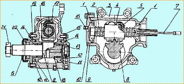
- - by turning the input shaft (Fig. 1), install the rack nut and sector 8 to one of the extreme positions (left or right);
- - determine the torque required to rotate the input shaft from the extreme position to the middle position (approximately an angle of 30°).
If the torque is less than 0.9 Nm, it is necessary to adjust the tension in bearings 1 by reducing the number of spacers 9.
After adjustment, the torque required to rotate the input shaft should be in the range of 0.9-1.5 Nm (0.10-0.15 kgf.m).
To check the presence of play in the gearing, you need to rotate the input shaft to set the rack nut and the gear sector to the middle position (the total number of revolutions of the input shaft is divided in half), install the bipod on the sector shaft 8.
By rocking the bipod in both directions, determine the presence of play (if there is play, a knock is heard in the gearing and, in addition, the sector shaft rotates, but the input shaft is stationary).
The presence of play can also be determined by turning the input shaft left and right as the torsion bar begins to twist, while locking the sector shaft.
To adjust the gearing, it is necessary to remove the covers 19 and 15 and turn the bearings 12 clockwise at the same angle (as viewed from the sector shaft) so as to eliminate any play in the gearing.
Instal the covers 15 and 19 in such a way that the pins 14 fit into the holes in the liners 12, located in the same diametrical plane with the threaded holes in the body 3 for fastening the covers.
If there is a slight discrepancy between the holes 11 and the threaded holes of the body 3, turn the liners 12 in one direction or the other until the above holes coincide, paying attention to the absence of a gap in the gearing.
Pins 14 should be located opposite each other along the same line.
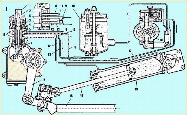
After adjustment, cover 15 (covers 10 and 16 are for the steering mechanism, Fig. 2) during installation can be rotated 90, 180 and 270 degrees relative to the original position.
After installing the covers, you can the torque required to rotate the input shaft in the middle position should be in the range of 2.9–4.5 Nm (0.29–0.45 kgcm)
After carrying out the adjustment work, install the steering mechanism on the car and, connecting it to the steering column and hydraulic cylinder, check the operation of the steering.
With proper adjustment (with adjusted steering linkage joints, front wheel hub bearings and front axle beam-steering knuckle pivot joints), the force on the steering wheel rim when turning the steered wheels in place on an asphalt surface should be 98 when the engine is running -118 N (10-12 kgf) and the free angle of rotation of the steering wheel is no more than 10-12˚.
During operation, it is allowed to increase the free play of the steering wheel, but not more than 18°.
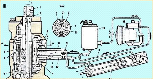
Adjustment of the rotation angles of sector 7 (Fig. 5), at which the pressure limiting valve 13 is activated, is carried out directly on the car as follows:
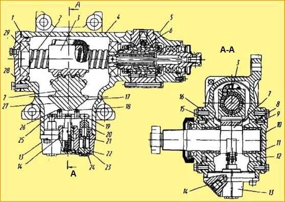
To increase the angles of rotation of sector 7 and, consequently, the steering wheels to the left to a given value, it is necessary to unscrew the lock nut 24 until it comes into contact with the body 23 and turn the plug 22 counterclockwise, while the nut 21 with the rod 20 and lever 19 will move down, ensuring the removal of roller 18 from the side face 17 of sector 7.
After adjustment, tighten locknut 24, holding plug 22 from turning.
To reduce the rotation angles of sector 7 and, consequently, the steered wheels to a given value to the left, it is necessary to unscrew the lock nut 24 until it comes into contact with the body 23 and turn the plug 22 clockwise, while the nut 21 with the rod 20 and the lever 19 will move upward, ensuring that roller 18 approaches the side face 17 of sector 7
After adjustment, tighten locknut 24, holding plug 21 from turning.
To increase or decrease the angle of rotation of the sector and, consequently, the steered wheels to a given value to the right, by a similar adjustment, the roller 26 with the lever 25 is removed or approaches the edge 27 of sector 7.