The cars are equipped with a speedometer, instrument cluster, two-needle pressure indicator, blocks of control and warning lamps, indicators indicating to the driver an extreme condition in a particular system, a set of sensors, switches and switches.
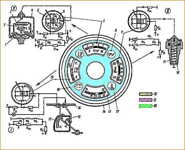
The instrument cluster (Fig. 1) includes indicators: fuel level, coolant temperature, engine oil pressure, voltage (voltmeter).
In addition, the combination includes indicators for coolant overheating, low (emergency) engine oil pressure and fuel reserve.
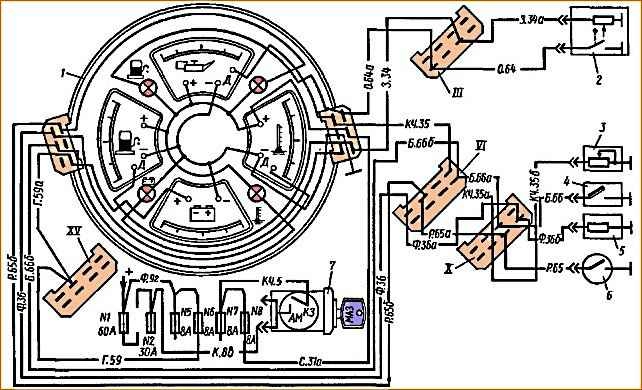
The connection diagram of the instrument cluster with sensors is shown in Fig. 2.
Each combination device consists of a plastic block 5 (see Fig. 1), carrying windings W1, W2, W3,
Between the windings there is an axis on which a permanent magnet and the pointer of the device are mounted. A permanent magnet 6 is pressed into one corner of the block.
In the absence of current in the circuit, the fields of these two magnets interact and place the arrow in the extreme left position.
When the current is turned on, the latter passes in series through the windings W2 and W3 and the temperature compensation resistance Rtk, which serves to stabilize the readings of the device when its temperature changes.
At the same time, current passes through the winding W1 and the resistance R of the sensor.
The resistance of the sensor changes: for the oil pressure and fuel level sensor by changing the position of the rheostat slider, for the temperature indicator sensor by changing the resistance of the thermistor itself.
When the sensor resistance changes, the current in winding W1 changes.
Since the current in the windings and W3 does not change its value, the position of the instrument needle depends on the interaction of the fields and windings W2 and W3 with the field of the winding W1, which changes its value.
The resulting field of all coils sets the arrow disk magnet to the appropriate position.
Two pressure indicators installed in the UK168 indicator work in a similar way and show the air pressure in the brake system circuits.

The speedometer, made in the same style as the instrument cluster, works in conjunction with a sensor installed on the gearbox (Fig. 3).
A three-way worm wheel 3 is mounted on the secondary shaft of the gearbox, which engages with a driven worm wheel 4, integral with the roller.
A spur gear 1 is mounted on the shaft shank, which meshes with gear 5 of the speedometer sensor drive.
Maintenance
Maintenance of instrumentation is reduced to maintaining instruments and sensors in good condition, for which it is necessary to wipe them weekly with a dry cloth instrument casings and sockets of control and warning lamp units, as well as ensure that the protective rubber covers fit securely on the sensor housings.
Improvements in the fit of the covers can lead to failure of the plug connection due to moisture and dirt.
Every 30 thousand kilometers during the next maintenance-2, it is necessary to remove the lubricant from the 2nd spur gears and the 5th speedometer (see Fig. 3) and replace it with a new one. CIATIM-201 lubricant is used to lubricate the gears.
Possible malfunctions of devices and ways to eliminate them
- Cause of malfunction
- Remedy
Fuel level, oil pressure and temperature gauges do not work
Voltage indicator works
- Fuse No. 8 burned out
- Replace the fuse
Voltage indicator does not work
- Fuse No. 6 burned out
- Replace the fuse
Indicator or signal lamps in the units do not light up
- Fuse No. 8 burned out
- Replace the fuse
The corresponding lamps in the block have burned out
- replace lamps
The current-carrying path on the unit board has burned out
- Inspect and correct the block
Underestimated or overestimated instrument readings (pressure, temperature and fuel gauges)
The corresponding sensor is faulty
- Replace sensor
Device faulty
- Replace device
The indicators for coolant overheating, fuel reserve or low oil pressure do not light up
The corresponding sensor has failed
- Replace sensor
Appliance repair
If the devices fail, you should first determine the serviceability of fuses No. 6 and 8. After making sure that the fuses are in good condition, you can look for the malfunction.
The simplest method for identifying faults in the instrumentation system is to sequentially replace first the sensors, then the indicator devices.
Before such a check, you need to make sure that the circuits from the devices to the sensors are in good condition. To do this, disconnect the wire from the sensors and short it to ground.
The arrows of the temperature and pressure indicators should in this case take the extreme right position on the scale.
When disconnecting the wires from ground, the arrows should return to their original position.
The deflection of the arrow and its return to its original position indicate the serviceability of the electrical circuit from the device to the sensor.
The arrow of the fuel level indicator should be set to zero on the scale when the wire at the sensor is shorted to ground.
If the instrument circuits are working properly, then the corresponding sensor is replaced.
If after this the device does not work normally, it should be replaced.
Device and sensors cannot be repaired, and if they fail, they are replaced entirely.
If necessary, assess the accuracy of instrument readings, you should be guided by the following data.
The voltage indicator has colored zones; on the red zone there is a strip corresponding to a voltage of 24 V, on the green - 28 V.
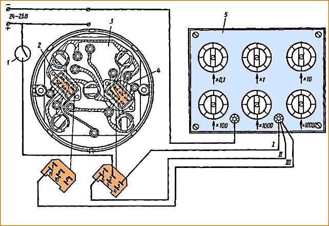
Pressure, fuel level and temperature gauges are checked using a control resistance according to the diagram shown in Fig. 4.
The devices are connected to a DC voltage source of 24 - 26 V and to a resistance store.
For this purpose, you can use the MKS-6 resistance store or any other that allows you to dial resistance from 50 to 560 Ohms at intervals of 0.5 Ohms.
Wires I, II and III from the combination devices are alternately connected to the resistance magazine and the resistances indicated in Table 1 are collected on the magazine.
Table 1.
Temperature indicator
Points to be checked - Resistance corresponding to the points to be checked (Ohms):
- 40 → 360-560;
- 80 → 134-150;
- 100 → 83-92;
- 120 → 52-61
Pressure indicator
Points to be checked - Resistance corresponding to the points to be checked (Ohms):
- 0 → 157;
- 6 → 63-71;
- 0 → 0-8
Fuel level indicator
Points to be checked - Resistance corresponding to the points to be checked (Ohms):
- 0 → 0-8;
- 0.5 → 36.5-43.5;
- 11 → 78-95
The fuel level indicator sensor has built-in contacts for the fuel reserve indicator.
In case of failure In order for the alarm to work, the orange wire of the plug block of the sensor installed in the tank must be shorted to ground.
In this case, if the circuit is working properly, the warning lamp installed in the instrument cluster should light up. If the lamp does not light up, the sensor is faulty and needs to be replaced.
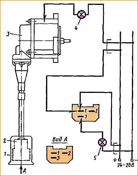
If the speedometer fails, first remove the sensor from the car and check it according to the diagram shown in Fig. 5.
Using test lamp 5, the serviceability of the sensor windings is checked by connecting voltage alternately to terminals 1 - 2; 2 - 3 and 1 - 3 sensor plugs.
In this case, the control lamp should be lit, which indicates that the sensor windings are working properly.
If the lamp does not light up in one of these measurements, the sensor is faulty and must be replaced. After checking the integrity of the windings, the sensor is checked for a short circuit to the housing.
Checking is carried out with a test lamp. In this case, the lamp should not light, which indicates that the sensor is working properly. If the speedometer does not work with a working sensor, the indicator device should be replaced.
")

")
")
")
")
")
")
")