Remove the cylinder head cover (650.1003256 - assembled).
Release the injector harness from the bracket brackets
Disconnect the electrical wires from the injectors.
Remove the injector harness bracket (650.3724126).
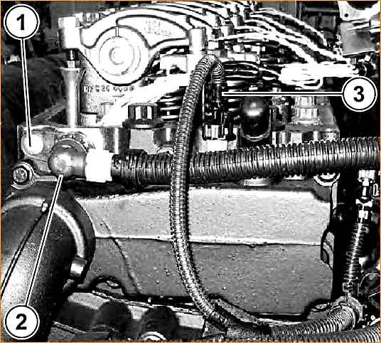
Disconnect the coolant temperature sensor (3) (650.1130556) (see Fig. 1).
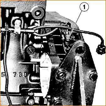
Unscrew the screw (1), remove the 1-shaped adapter (2) and the bundle of electrical wires (see Fig. 21).
Unscrew the rotary bolt (310200) with two copper washers (312381) securing the fuel drain pipe from the head.
Remove the fuel drain pipe (650.1104346).
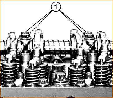
Unscrew 12 bolts (1) (see Fig. 2) securing the rocker arm axle struts (650.1007108).
Remove the rocker arms with the axle and struts assemblies (650.1007088).
Remove the rocker arms (650.1007176).
Arrange the parts in the required order.
Unscrew 14 M20 bolts (650.1003016) and 24 M14 bolts (650.1003017) securing the cylinder head.
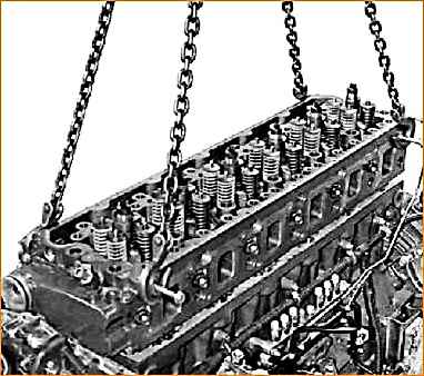
Remove the cylinder head (see Fig. 3).
Remove the cylinder head gasket (650.1003210).
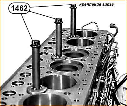
Secure the sleeves using tool 1462 (see Fig. 4).
Installing the YaMZ-650 cylinder head
1. Install the cylinder head gasket so that the manufacturer's mark is on top.
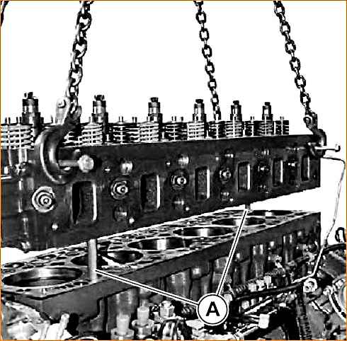
- 2. Check for presence of centering pins. (Use 2 headless screws (A) with a diameter of 14 mm, a length of 170 mm (see Fig. 5)).
- 3. Install the cylinder head.
- 4. Remove screws (A).
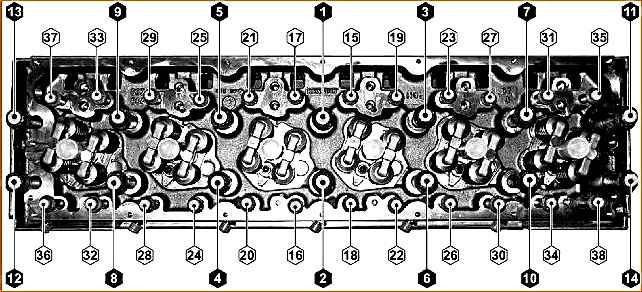
5. Install the cylinder head mounting bolts and tighten them in the order shown in Fig. 6.
Tighten in four steps using tools 2322 + 9777:
- - 1st step: bolts (1 - 14) M20x1.5 - 215 mm torque Mkr = 200 Nm;
- - 2nd step: bolts (15 - 38) M14x1.5 - 190 mm torque Mkr = 120 Nm;
- - 3rd step: loosen the M20 bolts, then tighten them to a torque of Mkr = 100 ± 10 Nm and tighten at an angle of 180˚ ± 6˚;
- - 4th step: loosen the M14 bolts, then tighten them to a torque of Mkr = 80 ± 10 Nm and tighten at an angle of 100˚ ± 6˚.
After tightening in the specified order, it is prohibited to tighten the bolts in the future.
Lubricate bolts:
- - since the new bolts are already lubricated, no additional lubrication is required;
- - when reusing or subsequently using bolts, lubricate the threads and under the bolt head with Loctite 542 sealant.
Installing rocker arms with axle and strut assembly
- 1. Lubricate the seating surfaces with oil.
- 2. Install the rocker arms.
- 3. Make sure that the centering pins are present.
- 4. Install the rocker arm axle.
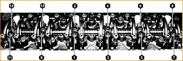
5. Tighten the bolts of the rocker arm axle struts according to the specified order and the recommended torque (see Fig. 7):
- - pre-tighten, observing the tightening procedure with torque Mkr = 20 ± 4 Nm;
- - tighten completely, observing the tightening torque order: Mkr = 40 ± 4 Nm plus an additional turn of 90˚ ± 6˚
- - check the tightening torque with a torque wrench Mkr = 100 ± 10 Nm.
Lubricating bolts: since new bolts already lubricated, no additional lubrication is required.
6. Install the injector harness bracket, tightening its fastening bolts to a torque of Mkr = 7.5 ± 1.5 Nm.
Adjusting the rocker arms
Check and adjust the clearances in the valve mechanism on a cold engine or no earlier than two hours after stopping it.
To check and adjust the clearances, it is necessary to set the piston of the adjustable cylinder to the top dead center (TDC) position on the compression stroke when the intake and exhaust valves are closed.
It is recommended to check and adjust the clearances in accordance with the operating order of the cylinders: 1 - 5 - 3 - 6 - 2 - 4.
Cylinders are numbered starting from the fan.
ATTENTION!
TDC on the compression stroke can be determined by the free rotation of the rocker arms of the intake and exhaust valves of the adjustable cylinder by hand.
If the rods are clamped and do not rotate, you need to turn the crankshaft 360˚ (one revolution).
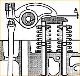
The gaps are checked using a feeler gauge, which must be inserted between the toe of the rocker arm and the yoke stop.
The size of the gap “A” (see Fig. 8) should be:
- - at the inlet 0.40 ± 0.05 mm,
- - at the outlet 0.70 ± 0.05 mm.
Use a torque wrench to check the tightening torque of the bolts securing the rocker arm axle struts (for additional tightening) and, if necessary, tighten them.
The tightening torque should be 80 - 100 Nm.
Adjust the gaps in the drive of the intake and exhaust valves of the 1st cylinder, for which it is necessary:
1. Disconnect and unscrew the engine speed sensor from the flywheel housing (1) (see Fig. 9).
- 2. Rotating the crankshaft using a rotary device, in the direction of rotation, set the piston of the 1st cylinder to TDC on the compression stroke (position 1 (see Fig. 10))
- 3. Loosen the locknut of the intake and exhaust valve rocker arm adjusting screw (alternately) and unscrew the screw half a turn.
- 4. Insert a feeler gauge of the required thickness between the toe of the rocker arm and the thrust surface of the yoke and, holding it in this position, screw in the adjusting screw so that the toe of the rocker arm comes into contact with the feeler gauge (adjustment is made for both intake and exhaust valves).
- 5. Holding the adjusting screw in this position, tighten the lock nut of the screw to a torque Mkr = 40 ± 8 Nm
- (when subsequently checking the gaps, a feeler gauge 0.45 mm thick at the inlet and 0.75 mm at the outlet should enter with little force (1 kgf), 0.35 mm thick at the inlet and 0.65 mm at the outlet - freely, without any effort).
- 6. then, turning the crankshaft sequentially 120˚ from position 1 (initial), adjust the gaps in cylinders 5, 3, 6, 2 and 4, respectively, in the same order.
- 7. Start the engine and listen to its operation. If the clearances are correctly adjusted, there should be no knocking in the valve mechanism.
")

")
")
")
")
")
")
")