The friction linings of the drum surface, as well as the bushings and necks of the expansion cams and the axles of the shoes are subject to the greatest wear in the service brakes
Disassembly of the front wheel brake is described in the article "Repair of the front axle and steering rods".
The thickness of the linings should be at least 7 mm with a lining reserve of 1 mm to the control flange or rivet head. The lining surface must not have any cracks, chipping or chips.
Install new linings and rivet them to the pads using a special device that ensures a tight fit of the lining to the pad surface.
The local gap between the pad and the lining must not exceed 0.1 mm.
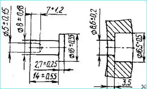
The shape of the rivet, its dimensions, and the dimensions of the hole for the rivet in the lining are shown in Fig. 1.

Fig.1. Rivet and rivet hole sizes in brake pads
Riveting is done from the pad side, and the rivet head should lie on a mandrel that ensures the head retains its shape during riveting.
Riveting can be done in a vice using a simple tool.
After riveting the linings, the pads assembled with the linings must be machined in pairs along the outside diameter to the nominal size, if the drum was not bored to the repair size.
If the drum was bored to one of the repair sizes, then the pads assembled with the linings must be machined to the same repair size number (see table).
The pads are machined on a lathe using a special installation that ensures the correct positioning of the pair of pads.
On cars equipped with ABS, the processing The linings must be produced on the front axle or rear (middle) axle using a machine model F - 306 from HUNGER (Germany) or similar.
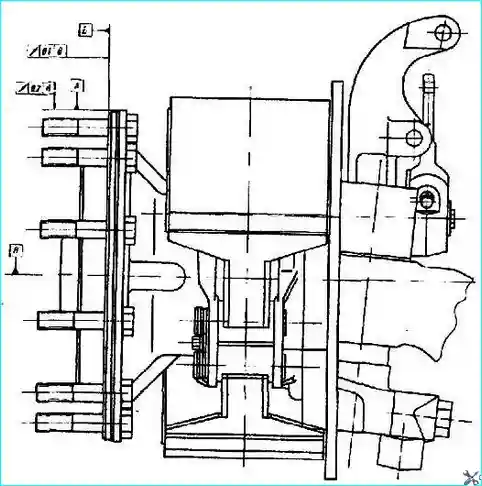
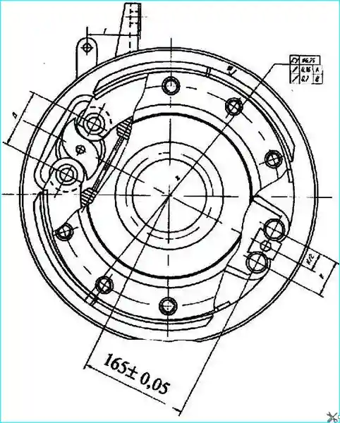
The processing diagram is shown in Fig. 2 and 3. The bases for processing are surfaces A and B of the wheel hub flange or the hub journal.
Before processing the brakes, it is necessary to check the runout of the base surfaces relative to the axis of rotation. Permissible runout:
- — surfaces "A" - 0.2 mm;
- — surfaces "B" - 0.1 mm.
If the runout of the base surfaces of the hub exceeds the permissible value, the hub must be replaced.
The procedure for processing the linings is as follows:
- — fix the adjusting lever motionless at a distance of G = 90 mm from the mating plane of the brake chamber mounting bracket using a device;
- — rotating the hexagon of the worm shaft of the adjusting lever, set the dimension "D" between the centers of the axes of the brake shoe rollers, equal to 95+1.0 mm (Fig. 3);

Fig. 2. Brake pad processing diagram
- — install and secure the centering flange of the processing machine on the wheel hub flange, based on surfaces A and B.
When using the wheel hub journal as a base — install and secure the centering sleeve of the machine on the journal;

Fig. 3. Brake pad processing scheme
- — process brake pads.
Installation of brake pads with linings made of different materials in one brake mechanism (on one bridge, on one axle) is not allowed.
Wear of the expander knuckle necks is allowed up to a diameter of 39.75 mm, expander knuckle bushings — up to a diameter of 40.10 mm.

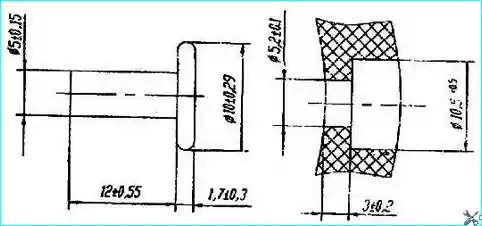
Fig. 4. Rivet and rivet hole dimensions in the brake shoes of the main parking brake
If these surfaces wear out beyond the specified values, the journals are welded and machined to a nominal diameter of (40-0.75) mm, and the bushings are replaced with new ones.
Wear of the bearing journals of the shoe axles is allowed up to a diameter of 31.88 mm.
Assemble the service brake in the reverse order. When installing the shoes, lubricate the axles with Litol-24 grease.
After installing the brake drum on the car, it is necessary to check its runout relative to the axis of rotation, which should not exceed 0.2 mm.
If the runout exceeds the specified value, the brake drum must be replaced.
When installing the adjusting lever, lubricate the splines of the expansion cam with Litol-24 or USSA grease.
On all-wheel drive vehicles equipped with a transmission parking brake, the brake linings are also subject to wear.
The requirements for their condition are the same as for the linings of the service brakes.
The differences are that the drum has a diameter of 300+0.15 mm, the pads are 100-1.0 mm wide and they are processed in a diameter of 300-0.2 mm.
The shape of the rivet, its dimensions, as well as the dimensions for the rivet in the lining are shown in Fig. 4.
The brake drum is statically balanced at the factory after processing. The permissible imbalance is no more than 50 g/cm.
The holes are drilled on the drum flange no more than 6 mm deep with a minimum pitch of 20 mm.
Nominal size:
- - inner diameter of the brake drum - 420+0.75 mm;
- - outer diameter of the brake shoes by linings - 420-0.57 mm
First repair size:
- - inner diameter of the brake drum - 421+0.75 mm;
- - outer diameter of the brake shoes by linings - 421-0.57 mm
Second repair size:
- - inner diameter of the brake drum - 422+0.75 mm;
- - outer diameter of the brake shoes by linings - 422-0.57 mm
Third repair size:
- - inner diameter of the brake drum - 423+0.75 mm;
- - outer diameter of the brake shoes by linings - 423-0.57 mm


