After removing the rear axle central gearbox from the vehicle for repair, disassemble it on a 500-600 mm high workbench in the following sequence:
- - remove the drive gear 5 (see Fig. 1) with the bearings assembled;
- - remove the stoppers and unscrew the nuts 20 of the differential bearings, loosening the bolts securing the covers 21;
- - remove the covers 21 of the differential bearings;
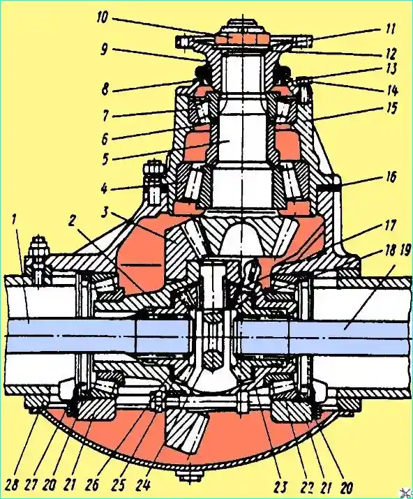
Fig. Central reduction gear of the rear axle: 1, 19 - half-shafts; 2, 23 - differential checkers; 3 - driven gear; 7, 12 - bearings; 5 - driving gear; 6, 16 - adjusting linings; 8 - oil seal; 9 - flange; 10 - nut; 11 - washer; 12 - sealing ring; 13 - cover; 14 - bolt; 15 - bearing housing; 17 - satellite; 18 - thrust ring; 20 - differential bearing nut; 21 - bearing cover; 24 - crosspiece; 25 - half-shaft gear; 26 - washer; 27 - bearing nut lock; 28 - axle housing
- - unscrew the nuts of the differential cup mounting bolts and disassemble the differential using the disassembling bolts (remove the satellites, half-axle gears, thrust washers);
- - remove, if necessary, the bearings 22 of the differential using a universal puller;
- - clamp the drive gear in a vice, the jaws of which are covered with soft metal pads, unscrew the nut and remove the flange 9 of the drive gear, cover 13 with the oil seal;
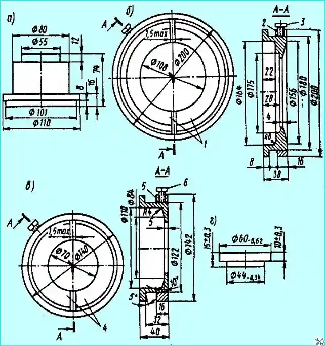
Fig. Set of mandrels for the universal puller for removing bearings of the middle and rear axles: (a) - support for removing the inner ring of the differential bearing and the inner ring of the outer bearing of the hub of the middle and rear axles; (b) - mandrel for removing the inner ring of the inner bearing of the drive gear; (c) - mandrel for removing the inner ring of the outer bearing of the cylindrical gear of the middle axle; (d) - support for removing the inner ring of the cylindrical bearing of the bridge differential; 1, 4 - half rings; 2, 5 - rings; 3, 6 - bolts
- - remove housing 15 with bearings; remove the inner race of the inner tapered bearing from the pinion shaft using a universal puller with a mandrel (Fig. 2);
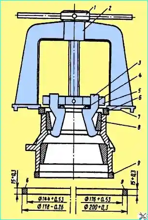
Fig. Removing the outer rings of bearings and the pinion of the middle and rear axles: 1 - nut; 2 - puller; 3 - grips; 4 - bolts; 5 - rolling pin; 6, 9 - rings; 7 - stop; 8 - outer bearing ring
- - if necessary, press out the outer bearing races of the pinion gear from the bearing housing using a puller (Fig. 3) without ring 6.
The disassembled parts of the central gearbox are washed and carefully inspected.
The condition of the working surfaces of the bearings is checked: they should not have chipped areas, cracks, dents, or peeling.
The rollers and separators should also not have any destruction or damage.
The gear teeth should not have chips or breaks, cracks, chipping of the cementation layer, or pitting. Burrs and nicks on the gear teeth must be removed and cleaned.
The wear of the bevel gear teeth by thickness is characterized by the value of the lateral clearance with correctly adjusted engagement (by contact patch).
The clearance is measured with an indicator from the large diameter side.
If the gears of the central reducer are noisy, a lateral clearance of 0.8-0.9 mm may serve as grounds for replacing the bevel gear pair.
If it is necessary to replace one of the gears, the driving and driven bevel gears must be replaced as a set, since at the factory they are matched in pairs by contact patch, lateral clearance and are marked with the same number.
When inspecting the differential parts, pay attention to the condition of the surface of the crosspiece necks, holes and spherical surfaces of the satellites, supporting surfaces of the axle gears of the support washers and end surfaces of the differential cups.
These surfaces should not have any burrs. In case of significant wear or weakening of the bronze bushing of the satellite, it must be replaced.
The new bushing should be processed after pressing it into the satellite to a diameter of 32+0.05 mm.
If the bronze support washers of the half-axle gears are significantly worn, the latter must be replaced.
The thickness of the new bronze washers is 1.5 mm. The differential cups, if it is necessary to replace one of them, are replaced as a set.
The gearbox housing is made of malleable cast iron KCh 37-12.
The main defects for which the crankcase is restored are wear of the holes for the bearing housing and the hole for the rear bearing of the pinion shaft, damage to the threads for the differential bearing nuts.
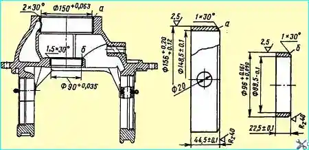
Fig. Repair bushings of the gearbox housing: (a) - for the bearing housing of the pinion shaft; (b) - for the rear bearing
When the hole for the bearing housing of the pinion shaft is worn to a diameter of more than 150.10 mm, it is bored to a size of 156+0.08 mm to a depth of 44+0.1 mm.
Press the repair sleeve (Fig. 4) into the bored hole until it stops against the flange, ensuring an interference fit within 0.08-0.12 mm and aligning the hole in the sleeve with the oil channel in the bearing housing.
Bore the hole in the sleeve to a diameter of 150+0.063 mm, trim the end of the sleeve flush with the base metal and bore a 2x30° chamfer.
The hole for the rear bearing of the pinion shaft, worn to a diameter of more than 90.07 mm, restored by installing a repair bushing.
The worn hole is bored on a lathe in the faceplate to a diameter of 96+0.07 mm to a depth of 22+0.1 mm.
Then press the repair bushing until it stops against the flange, ensuring an interference fit within 0.05-0.08 mm, and bore the hole in the bushing to a diameter of 90+0.035 mm.
The end of the bushing is cut flush with the base metal and a chamfer of 1.5x30° is bored.
If the thread for the adjusting nuts of the differential bearings is damaged, bore: the damaged thread for the nut of the left bearing to 135.9-02 mm to a depth of 21 mm, the chamfer 1.5x45°, a 5 mm wide groove up to 139 mm deep by 21 mm and cut a repair thread M138x2 to exit into the groove.
If the thread under the nut of the right bearing is damaged, bore out: the damaged thread up to 155.9 mm to a depth of 19 mm, chamfer 1.5 x 45°, a 5 mm wide groove up to a diameter of 159 mm to a depth of 19 mm and cut a repair thread M158 x 2 to exit into the groove.
When repairing the gearbox housing, the following basic requirements for the relative position of the surfaces must be met:
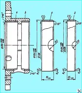
Fig. Repair bushings of the bearing housing of the drive pinion shaft: (a) - under the outer ring of the front roller bearing; (b) - under the outer ring of the rear roller bearing
- - the runout of the surface of the hole for the rear bearing of the pinion shaft relative to the surface of the hole for the bearing housing is allowed to be no more than 0.05 mm;
- - the runout of the surfaces for the differential bearings relative to each other is allowed to be no more than 0.05 mm;
- - the runout of the threaded surfaces for the adjusting nuts of the differential bearings relative to the surfaces of the holes for the differential bearings should not exceed 0.2 mm;
- - the non-perpendicularity of the axis of the surfaces of the holes for the rear bearing and the bearing housing of the pinion shaft relative to the surfaces of the holes for the differential bearings should not exceed 0.05 mm over a length of 100 mm;
- - the axis of the surfaces of the holes for the rear bearing and the bearing housing of the pinion shaft should intersect with the axis of the surfaces of the holes for the differential bearings with deviation of no more than 0.05 mm.
The bearing housing of the pinion shaft is made of malleable cast iron KCh 37-12.
The housing is restored when the holes for the outer rings of the roller bearings of the pinion shaft are worn out and when the housing journal is worn out.
If there are cracks and breaks, the housing is rejected.
When the hole for the outer ring of the front roller bearing is worn to a diameter of more than 130.0 mm, it is restored by installing a repair sleeve.
To do this, bore the holes to a size of 136+0.08 mm to a depth of (32± 0.3) mm and make a chamfer of 1 x 45°.
Then press the repair sleeve into the hole. (Fig. 5) until it stops against the jumper, ensuring an interference fit of 0.05-0.08 mm and aligning the holes in the bushing with the hole in the crankcase.
A hole with a diameter of 12 mm is drilled in the bushing through the hole in the bearing housing and the hole in the pressed bushing is bored to a diameter of 130-0.028-0.068 mm, removing a chamfer of 2x45˚
If the hole for the outer ring of the rear roller bearing is worn to a diameter of more than 130.0 mm, it is also restored by installing a repair bushing (see Fig. 5) in the previously specified sequence.
The runout of the surfaces of the holes for the outer rings of the roller bearings of the drive gear relative to each other should not exceed 0.05 mm.
The holes are machined on a lathe, ensuring installation on the crankcase landing journal. The landing journal, worn to a diameter of tra less than 150.02 mm, are restored only by surfacing using a special technology.
The differential box cups are made of malleable cast iron KCh 37-12.
The cups are restored: in case of scoring, scratches or uneven wear of the end face under the axle gear washer; wear of the holes under the crosspiece pins; scoring, scratches or wear of the spherical surface under the satellite washers; wear of the holes under the axle gear journal; wear of the journals under the differential bearings and for the right cup in case of wear of the journal under the driven gear.
The cups are rejected if there are cracks or breaks.
The left and right cups are structurally different from each other. Therefore, their repair according to distinctive defects and sizes will be considered separately.
Left cup
In case of scoring, scoring or uneven wear of the end face of the bearing surface under the axle gear washer to a size of less than 47.2 mm from the axis of the holes for the differential crosspiece pins to the bearing surface under the axle gear, the end face is turned to remove scoring and wear marks to one of the repair sizes given in Table 1.
The surface roughness should be Rz20.
The bearing surface is machined in the faceplate on a lathe, based on the mating surface with the right cup.
It should be noted that for performing turning work, the mating surfaces between them are taken as the base for both cups of the differential box, and for the right cup, in addition, an additional base can be taken - a neck under the conical driven gear and only if there is a need to replace the gear.
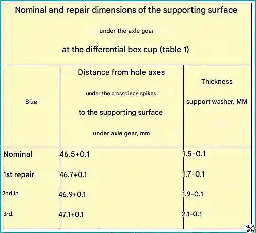
The left and right differential case cups are rejected if the distance from the axes of the holes for the crosspiece pins to the supporting surface for the axle shaft gear is more than 47.2 mm.
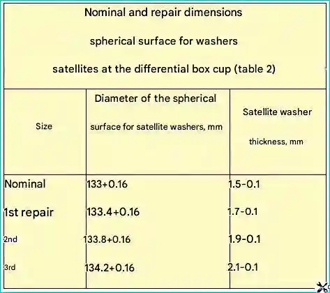
If there are scratches, scoring or wear on the spherical surface for the satellite washers to a size less than 134.36 mm, the spherical surface is bored to one of the repair sizes given in the table and the surface roughness Rz 20.
The left and right cups are rejected if the size is more than 134.36 mm.
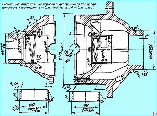
The hole for the axle gear journal, worn to a size greater than 68.1 mm, is restored by installing a bushing.
To do this, the cup is installed in the faceplate, the hole is bored to Ø 73+0.06 mm to a depth of 27 mm and a surface roughness of 2.5 μm and a chamfer of 1x45° is removed.
Then press in repair bushing (Fig. 6) into the bored hole, bore the hole in the bushing to Ø 68+0.06 mm and a roughness of 2.5 μm, trim the end of the bushing flush with the plane of the base metal, ensuring a roughness of 2.5 μm, bore a 2x45° chamfer on the end of the bushing and cut a helical groove in the bushing hole with a step of 20 mm, a depth of 1-0.5 mm, maintaining the groove radius of (2±0.5) mm.
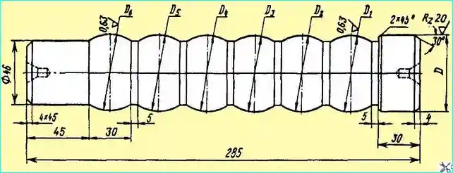
Fig. Piercing for expanding the journal for differential bearings
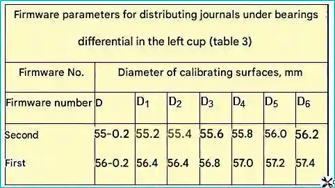
When the journal for the differential bearing wears to a diameter of less than 75.01 mm, it is restored by expanding.
To do this, the cup is installed with the parting plane on the table of a hydraulic press and the journal is expanded to Ø 75.2 mm by piercing (Fig. 7), the parameters of which are given in Table 3.
Then the surface of the journal is ground to Ø 75 mm and a surface roughness of 1.25 μm, providing a fillet with a radius of 2-2.5 mm.
The holes for the crosspiece tenons, worn to a diameter of more than 25.08 mm, are reamed to a repair size or restored by surfacing.
Before surfacing, the holes in the left and right cups of the differential box are cleaned to a metallic shine and surfacing alternately holes up to Ø 22 mm with an electrode of Ø 4 mm.
Then install the left cup on the studs of the right one, simultaneously aligning the holes with the mounting pins, and screw the nuts onto the studs, tightening them until they stop.
The assembled cups are secured in the jig and on a radial drilling machine, drill holes up to Ø 23 mm, countersink two holes up to Ø 24.8 mm in a line and ream two holes up to Ø 25 + 0.023 mm in a line and a surface roughness of 2.5 μm.
After this, disassemble the cups and file the sharp edges of the holes for the crosspiece tenons with a chamfer of 0.5 x 45 °.
Before disassembling the cups, it is necessary to mark their mutual position with paint, which are observed during assembly. Then the differential box cups are assembled.
Right cup
Wear of the spherical surface under the satellite washers, the bearing surface under the half-axle gear washer and the holes for the journal of the axle gear of the right cup are restored in the same way as for the left cup.
If the journal for the differential bearing is worn to a diameter of less than 100.01 mm, it is restored by vibratory arc surfacing to 103+0.5 with wire Sv-Ø,8 1.6 mm at a part rotation speed of 2.5 min1, a wire feed speed of 1.3 m/min and a surfacing step of 2.5 mm/rev, without cooling.
A similar method can be used to restore the journal for the bearing of the left cup in cases where the expansion does not provide the required size.
The welded journal of the right cup is turned down to 100.8 mm, providing a fillet radius of (20.5) mm and a chamfer of 2x30° on the end of the journal.
Then the journal is finally ground to nominal 100 mm and surface roughness of 1.25 μm.
The worn journal under the driven bevel gear to diameter less than 178.0 mm are restored by vibratory arc surfacing, without cooling.
The neck is surfaced to Ø 181 mm with Sv-0.8 wire Ø1.6 mm at a wire feed rate of 1.3 m/min, a part rotation speed of 1.1 min1 and a surfacing step of 2.5 mm/rev.
The surfacing neck is turned to Ø 178.3 mm, providing a fillet with a radius of no more than 1.5 mm, and ground to a nominal Ø 178-0.027 mm and a surface roughness of 2.5 μm.
When restoring the differential box cups, the following requirements for the relative position of the surfaces must be met:
- - the axis of the surface of the holes for the tenons of the differential crosspiece must be in the plane of the joint of the cups - permissible deviation is not more than 0.05 mm;
- - the axes of the surfaces of the holes for the crosspiece pins must be perpendicular to each other with a deviation of not more than 0.05 mm;
- - the displacement of the center of the axes of the surfaces of the holes for the crosspiece pins of the differential relative to the axis of the surfaces under the journals of the half-axle gears must not exceed 1± 0.05 mm;
- - the non-concentricity of the mating surfaces of the cups and the journal for the differential bearing is allowed to be no more than 0.03 mm;
- - the non-perpendicularity of the supporting surface for the half-axle gear and the surface under the journal of the half-axle gear is allowed to be no more than 0.05 mm;
- - the non-perpendicularity of the surfaces of the differential bearing stop, the cup connector and the flange of the bevel driven gear (for the right cup) relative to the mating surface of the cups is allowed to be no more than ,05 mm;
- - the non-concentricity of the spherical surface under the satellite washers, the surface under the axle gear journal and the surface of the neck under the driven bevel gear (for the right cup) relative to the mating surfaces should not exceed 0.05 mm;
- - the center of the spherical surface should lie in the plane of the cup joint with a deviation of no more than 0.05 mm.
The rear wheel hub and the spacer ring of the hub bearings are made of 40L steel. The end surfaces M and H of the spacer ring (Fig. 8) are hardened to a hardness of at least HRC 40 to a depth of 2-5 mm.
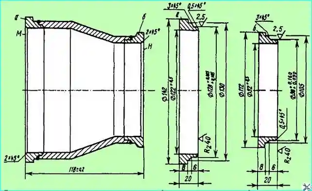
Fig. Repair bushings of the spacer ring of the rear wheel hub bearings: (a) - from the side of mating with the outer bearing; (b) - from the side of the mating with the inner bearing
The hub is restored when the holes for the outer rings of the inner and outer bearings are worn out.
When the hole for the outer ring of the inner bearing is worn to a diameter of more than 159.99 mm, it is restored by installing a bushing.
To do this, the hole for the bushing is bored to Ø 166+0.08 mm to a depth of 71 mm and a surface roughness of 2.5 μm, a chamfer of 1x45° is removed, the bushing is pressed in with an outer 166 mm, ensuring an interference fit within 0.08-0.20 mm, the hole in the bushing is bored for the outer ring of the bearing to 160 mm and a surface roughness of 2.5 μm and a chamfer of 2 x 30° is removed on the end bushings.
The holes are machined on a lathe in a faceplate, based on a surface of Ø 300+0.084 mm, the runout of which relative to the surface of the hole for the bearing ring should not exceed 0.1 mm.
The hole for the outer ring of the outer bearing, worn to a diameter of more than 214.98 mm, is restored by installing a bushing or vibratory arc surfacing.
When restoring a hole by installing a bushing, the hole is bored to Ø 221+0.09 mm over a length of 40 mm and a surface roughness of 2.5 μm.
Then a repair bushing with an outer Ø of 221 mm is pressed into the bored hole until it stops against the flange, ensuring an interference fit within 0.1-0.25 mm, bore the hole in the bushing to Ø 215 mm and a surface roughness of 2.5 μm and a 2x30° chamfer on the end of the bushing, simultaneously facing the bushing flush with the hub metal.
When boring, the hub is secured to the faceplate, based on the landing surface of the brake drum.
When restoring the hole for the outer ring of the outer bearing by surfacing, the hole is bored to Ø 217+0.5 mm over a length of 40 mm, the surface of the hole is surfacing to Ø 211 mm with OVS wire Ø 1.8 mm at a part rotation speed of 1.2 min1, a wire feed rate of 1.2 m/min and a surfacing step of 2.5 mm/rev without cooling. The surfacing is performed in several layers.
The surfacing hole is bored to Ø 215’ mm, providing a fillet with a radius of 1.5 mm at the end of the bore and a surface roughness of 2.5 μm.
The axes of the surfaces of the holes for the outer rings of the bearings should lie on the same straight line with a deviation of no more than 0.05 mm.
The spacer sleeve is restored when there is wear, scratches and wear of the end surfaces to a size of less than 118.0 mm (see Fig. 8).
If there is such a defect on the side of the mating surface of the end of the ring with the inner bearing, a repair sleeve is installed (see Fig. 8).
To do this, cut off the end of the ring, provide a size of 106 mm to the second end, bore the hole for the repair sleeve to 0 98+0.07 mm to a depth of 7 mm and a surface roughness of 2.5 μm, remove a chamfer of 0.5x45° in the hole and a chamfer of 2x45° on the outer surface for welding.
Then the sleeve is pressed into the hole and welded with a circular seam using Sv-0.8 wire Ø 1.6 mm at a wire feed rate of 1.2 m/min and a rotation frequency of the part of 1.5 min.
The surfacing 4 is carried out under a layer of AN-348A flux. Then the end of the sleeve is trimmed to a size of 119-0.1 mm from the opposite end, a chamfer of 2.0 x 45 is bored and the surface of the end of the ring is annealed with a T.V. h. to a depth of 2.5-5.0 mm to a hardness of at least HRG 40.
After hardening, the end face surface of the ring is ground on a surface grinding machine, providing a total length of the spacer ring (118.5±0.2) mm and a surface roughness of 2.5.
It is allowed to surfacing the worn surface of the end face of the ring to a size of 120.5 mm with an electrode of the UONI-13/55 0 4 mm brand with subsequent processing described for the option of installing the sleeve.
The second end face of the spacer sleeve is restored in a similar manner, observing the entire sequence and dimensions, with the exception of boring the hole for the repair sleeve (see Fig. 8) to Ø 128+0.08 mm.
The surfaces of the ends M and H must be parallel to each other with a deviation of no more than 0.05 mm.
When assembling the gearbox, the mounting and mating surfaces of the parts are lubricated with oil, the sealing gaskets - with paste or nitro paint, and the working edges of the oil seals - with Litol-24 grease.
The bearings are washed with kerosene or kerosene with subsequent lubrication with working oil.
To assemble the central gearbox first, it is necessary to assemble the drive gear, for which:
- - press the oil seal 8 (see Fig. 1) into the bearing housing cover to a depth of 6 mm from the front end of the cover using the mandrel shown in Fig. 9, avoiding skewing of the oil seal and its deformation;
- - press the outer races of bearings 4, 7 (see Fig. 1) into the bearing housing until they stop against the flange. In this case, it is recommended to - heat the bearing housing in oil to a temperature of 60-70 ° C;
- - press the inner tapered bearing 4 onto the shaft of the leading bevel gear until it stops;
- - place the spacer ring, adjusting linings 6 on the gear shaft, install the gear in the bearing housing;
- - install the second tapered bearing 7, flange 9, sealing ring 12, washer 11 on the gear shaft and tighten the flange nut 10 to a torque of 450-600 N m (45-60 kgf/m);
- - adjust the tapered bearings with preliminary tension.
After the final assembly of the leading gear, the differential should be assembled, for which:
- - press the bearing onto the right cup of the differential until it stops with using a mandrel (Fig. 9);
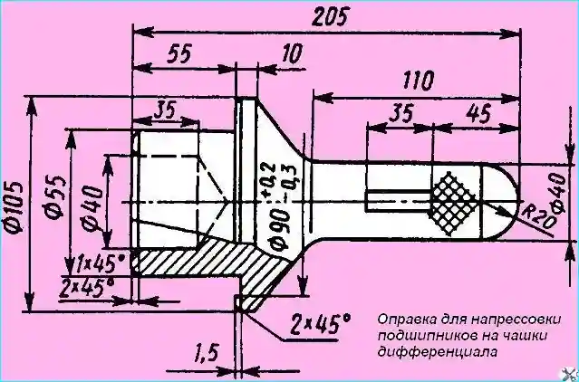
Fig. Mandrel for pressing bearings onto differential cups
- - install a bronze washer into the right differential cup, lubricating it with liquid oil;
- - insert a half-axle gear lubricated with liquid oil into the bore of the right cup. A correctly installed axle gear should rotate easily by hand;
lubricate the differential crosspiece studs with liquid oil;
- - put the thrust washers of the satellite bushings on the studs, the satellites with the bushings and put on the support washers of the satellites, having lubricated the specified parts;
- - install the crosspiece with the satellites and washers in the sockets of the right cup, pressing the crosspiece to the seating sockets of the cup, check the lateral clearance between the gear teeth and ease of rotation.
When turning one (any) or two satellites by hand, the others, as well as the axle gear, should also turn;
- - press the bearing onto the left differential cup until it stops using the mandrel shown in Fig. 9, and gear 3 (see Fig. 1) onto the cup pins until they stop;
- - install the support washer and half-axle gear into the left cup (similar to installing them into the right cup);
- - transfer the crosspiece with satellites and washers to the left cup (similar to the right cup), check the side clearance;
- - holding the half-axle gear with your fingers, place the right cup on the left through the hole for the half-axle in the right cup, putting it on the pins and aligning the numbers of the differential cup kit.
Install the cup mounting bolts and lock plates so that they cover the pins, tighten the nuts to a torque of 210-260 Nm (21-26 kgf m), bend the plates on the edge of the nuts;
- - insert splined reference in one of the axle gears and make several turns - the differential gears should rotate easily, without knocking or jamming from the force of the hand.
The general assembly of the central gearbox should be carried out in the following order:
- - install the gearbox housing on the device so that the hole for the cup of the drive gear 5 (see Fig. 1) is at the bottom;
- - lubricate the differential bearings with liquid grease, put on the outer races and install the previously assembled differential in the bearing seats of the housing;
- - install the centering pins (bushings) in the bearing support seats, put on the covers, lock plates and pre-tighten the bolts;
- - tighten the nuts 20;
- - adjust the differential bearings with a preliminary tension;
- - turn the gearbox housing so that it is possible to install the drive pinion assembly with bearings in the housing;
- - adjust the engagement of the bevel gears;
- - tighten the cover bolts with a torque of 250-280 Nm (25-28 kgf), then lock them with plates, bending them at the edge of the bolts and the cover;
- - fully tighten all the nuts of the studs securing the drive pinion bearing housing to the gearbox housing;
- - install the stoppers 27 of the differential bearing nuts and press them with bolts and spring washers.
The central gearbox of the middle bridge is disassembled during repair in the following sequence:
- - remove the differential lock mechanism 20;
- - unscrew the bolts and remove crankcase assembly with axle drive shaft 30 and center differential 29: when removing the crankcase, it is necessary to rotate the flange to ensure that the differential comes out from behind the gear;
- - remove flange 17, unscrew cover mounting bolts 15, remove the cup with bearing 14 from shaft 30 and differential lock coupling 19 using a universal puller;
- - unscrew the bolts securing the neck cups of center differential 29 and remove the cup with gear and bearing from shaft 30
- - remove the retaining ring, pin and unscrew the crosspiece mounting nut 28;
- - remove crosspiece 28 from shaft 3, remove gear 25 assembled with bearings 13 using a puller;
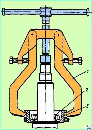
Fig. Removing the inner ring of the outer bearing of the cylindrical gear of the middle bridge: 1 - puller; 2 - inner ring of the bearing; 3 - mandrel assembly
- - remove the inner ring of the outer bearing of the cylindrical gear using a puller with a mandrel 3 (Fig. 10) during partial disassembly, when it is necessary to remove only the shaft 30 (see Fig. 11) of the axle drive assembly with the center differential 29, unscrew the cover mounting bolts 15 and remove the axle drive shaft together with the center differential.
In this case, to remove, it is necessary to turn the shaft 30 to adjust the chamfer on the differential cups so that the cups do not touch the gear 10.
To remove, if necessary, the inner ring of the cylindrical bearing of the center differential, use a universal puller;
- - unscrew the nuts and remove the drive gear 3 with the housing 8 of the bearings and the cylindrical gear 10 assembled;
- - clamp the leading bevel gear 3 in a vice (the jaws of which are covered with soft metal pads), unscrew the nut 11 and remove the gear 10;
- - remove the inner ring of the inner tapered bearing from the shaft of the leading gear 3 using a puller with a mandrel 6 (see Fig. 2);
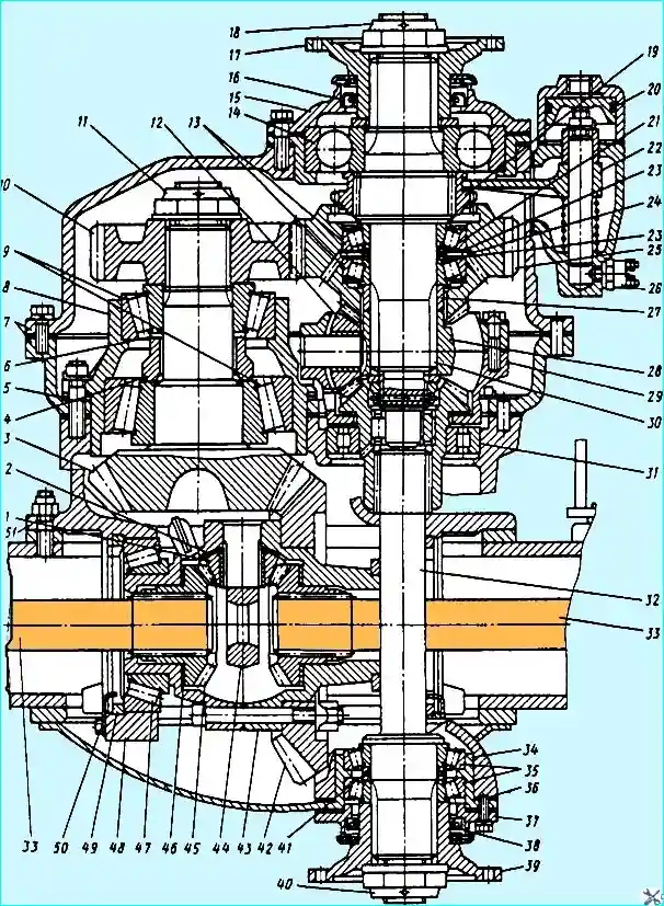
Fig. Central gearbox of the middle bridge: 1, 12 - satellites; 2, 46 - support washers; 3 - leading bevel gear; 4, 27 - spacer sleeves; 5 - adjusting linings; 6, 21, 41 - adjusting washers; 7 - housings; 8 - bearing housing; 9, 11, 14, 31, 35, 47 - bearings; 10 - driven cylindrical gear; 11, 18, 40 - nuts; 15, 37 - covers; 16, 38 - oil seals; 17, 39 - flanges; 19 - center differential lock clutch; 20 - center differential lock mechanism; 22 clutch engagement fork; 23 - thrust washer; 4 - lock washer; 25 - driving cylindrical gear; 26 - center differential lock engagement sensor; 28, 44 - crosspieces; 29 - center differential; 30 - axle drive shaft; 32 - output shaft; 33 - half-shaft; 34 cup; 36 - bolt; 42 - driven gear; 43 - interwheel differential; 45 - half-shaft gear; 48 - cover; 49 - differential bearing nut; 50 - stopper; 51 - gearbox housing
- - if necessary, press out the outer rings of the bearings 9 from the housing 8 (see Fig. 11) using a puller (see Fig. 3);
- - remove the stoppers 50 (see Fig. 11) and the covers 48 of the bearings 47 of the differential;
- - remove the differential 43 as an assembly;
- - unscrew the nuts of the differential cup mounting bolts and disassemble the differential 43 using dismantling bolts, remove the satellites 1, half-axle gears 45, washers 46;
- - remove the bearings 47 of the differential using a puller if necessary;
- - unscrew the bolts 36 (see Fig. 11) and remove the shaft 32 as an assembly with the bearings 35, unscrew nut 40 and disassemble the shaft;
- - if necessary, disassemble the differential lock mechanism 20.
The disassembled parts of the gearbox must be washed and the condition of the working surfaces of the bearings and gears must be checked.
The gear teeth must not have chips, cracks, chipping of the cementation layer, or severe wear.
If the teeth wear out slightly stepwise, the steps are cleaned; it is also necessary to clean up nicks and burrs on the gear teeth.
The wear of the teeth of bevel gears by thickness is characterized by the size of the lateral clearance. The gap is measured with an indicator from the side of the larger diameter.
If the gears of the central reduction gear are making increased noise, a lateral gap of 0.8 mm may serve as a basis for replacing the bevel gear pair.
If necessary, the leading and driven bevel gears are replaced as a set, since at the factory they are selected in pairs based on the contact patch and lateral gap.
When replacing bevel gears, it is necessary to install a pair of gears of the middle bridge. Installation of rear axle gears is not allowed.
When inspecting the differential parts, pay attention to the condition of the surface of the crosspiece journals, holes and spherical surfaces of the satellites, bearing surfaces of the axle gears, bronze support washers and end surfaces of the differential cups.
These surfaces should not have any scoring or significant wear.
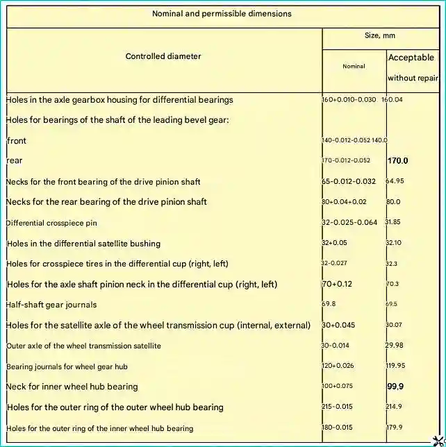
When inspecting the parts of the rear and middle axles of the vehicle, use the nominal and permissible dimensions given in Table 4.
In case of significant wear or weakening of the satellite bushing fit, it must be replaced.
The new bushing must be processed after pressing it into the satellite to a diameter of 32+0.05mm.
In case of significant wear of the bronze support washers of the axle gears and satellites, the washers must be replaced. The thickness of the new bronze washers is 1.5 mm.
Before assembly, the mounting and mating surfaces of the gearbox parts must be lubricated with working oil, it is recommended to lubricate the sealing gaskets with plastic grease, sealing paste or nitro paint, and the working edges of the oil seals with Litol-24 grease.
The bearings must be washed in kerosene, then lubricated with working oil.
The assembled rear axle after repair must be tested on a stand.
Before testing, industrial oil 12 or 20, heated to a temperature of 60 ° C, is poured into the crankcases of the wheel gear and rear axle.
To pour oil into the wheel gear, it is necessary to remove the small cover and pour oil to the lower edge of the hole in the large cover.
In addition, grease can be poured into the wheel gear through the hole in the drain plugs, turning the hub so that the edge of the hole for the small cover is on the same horizontal line with the hole for the drain plug.
In this case, oil is poured to the level of the hole for the drain plug.
Oil is poured into the rear axle housing through the hole in the rear cover to the edge of the hole.
A coupling head is screwed into the hole in the rear axle housing under the breather, a hose is connected and the rear axle is filled with air, bringing the pressure to 0.02-0.04 MPa (0.2-0.4 kg/cm²).
If there are oil leaks along welded joints, they are welded, and if oil is leaking along flange joints, they are tightened with bolts and.
Then test the rear axle at a drive pinion shaft speed of 900-1500 min¹ according to the mode given in the table.
Rear axle test mode:
- - Braking torque on each axle shaft, kgf/m without load -, test duration 5 min;
- - Braking torque on each axle shaft, under load - 50 kgf/m, test duration 10 min;
To test the operation of the differential and wheel transmission, it is necessary to fully brake the drums one by one for 0.5-1.0 min, supplying compressed air to the corresponding brake chamber.
When testing the rear axle, the following are not allowed: increased, uneven gear noise, gear knocking, differential jamming, heating of the brake drums, oil leakage through seals and joints.
Slight oil stains are allowed at joints and seals.
At the end of the test, the degree of heating of the gearbox bearings, differential and wheel hubs is checked by touch.
A slight increase in temperature of the corresponding parts of the housings and hubs is allowed.
If excessive heating occurs, it is necessary to check the tightening and adjustment of the bearings.
Defects identified during the rear axle test are eliminated and the rear axle is re-tested on the stand.


