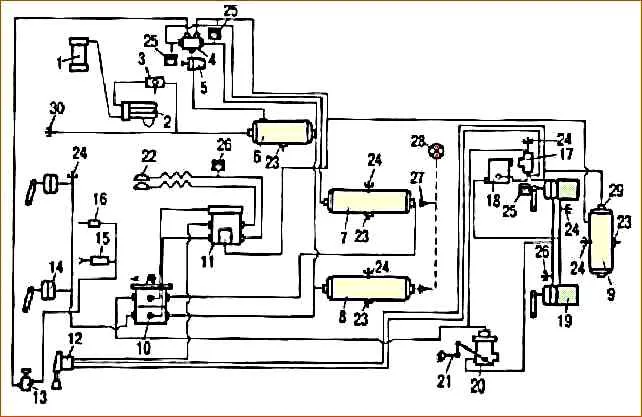
A schematic diagram of the pneumatic drive of brakes for three-axle vehicles is shown in Fig. 1, biaxial - in Fig. 2
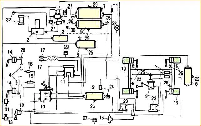
A schematic diagram of the pneumatic brake drive of MAZ-631705, 631708, 642505, 642508 vehicles with a transmission parking brake is shown in Fig. 3, car MAZ-53 1605 with a transmission parking brake - in Fig. 4.
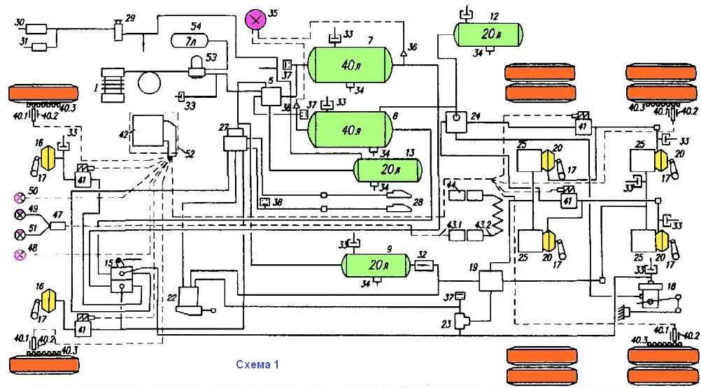
Principal diagram of the pneumatic drive of the brakes: 1 - compressor; 5 - 4-circuit protective valve; 7 - front circuit receiver; 8 - rear circuit receiver; 9 - parking (spare) brake and trailer receiver; 12 - rear circuit receiver; 13 - consumer receiver; 15 - brake valve; 16 - front brake chamber; 17 - brake knuckle lever; 18 brake force regulator; 19 - accelerator valve; 20 - brake chambers of the rear brakes; 22 - manual brake valve; 23 - dual-line valve; 24 - accelerator valve; 25 - spring cylinders; 27 - trailer control valve; 28 - connecting head; 29 - auxiliary brake valve; 30 - cylinder for auxiliary brake flap drive; 31 - fuel shut-off drive cylinder (optional); 32 - check valve; 33 - control valve; 34 - condensate drain valve; 35 - pressure gauge; 36 - pressure sensor of receivers; 38 - pressure gauge brake signal switch; 39 - system fault indicator; 40 - wheel dynamic condition sensor; 40.1 sensitive element; 40.2 - clamping sleeve of the sensitive element; 40.3 - sensor rotor (inductor); 41 - brake pressure modulator; 42 - electronic unit; 43 - connection to trailer ABS; 43.1 - cable with connector; 43.2 - spiral cable; 44 - parking socket; 47 - information module; 48 - tractor ABS warning lamp; 49 - trailer ABS warning lamp; 50 - ABS diagnostic lamp; 51 - trailer ABS power control lamp; 52 - mounting board; 53 - pressure regulator with adsorber; 54 - regeneration receiver
Diagram of pneumatic brake drive for three-axle vehicles
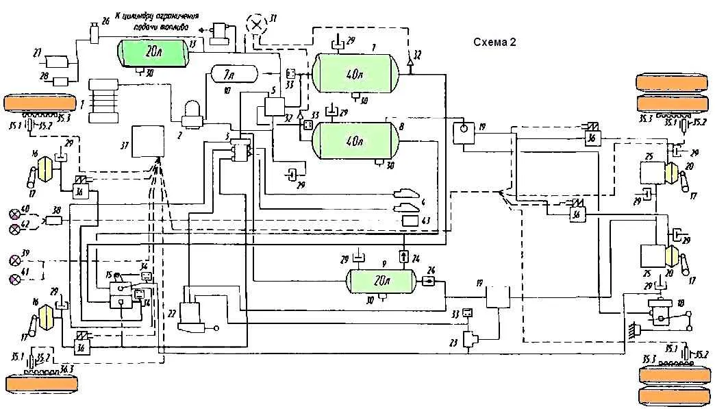
Principal diagram of the pneumatic drive of the brakes; 1 - compressor; 2 - pressure regulator with adsorber; 3 - trailer brake control valve; 4 - connecting head; 5 - 4-circuit protective valve; 7 - front circuit receiver; 8 - rear circuit receiver; 9 - parking (spare) brake and trailer receiver; 12 - regeneration receiver; (3 - consumer receiver; 15 - brake valve; 16 - front brake chamber; 17 - brake knuckle lever; 18 - brake force regulator; 19 - accelerator valve; 20 - rear brake brake chambers; 22 - hand brake valve; 23 - valve two-line; 24 - check valve; 25 - spring cylinders; 26 - auxiliary brake valve; 27 - auxiliary brake flap drive cylinder; 28 - fuel supply shut-off drive cylinder; 29 - control output valve; 30 - condensate drain valve; 31 - pressure gauge; 32 - pressure sensor of receivers; 33 - minimum pressure sensor; 34 - pressure gauge brake signal switch; 35.1 - sensitive element; 35.2 - clamping sleeve of the sensitive element; 35.3 sensor rotor (inductor); 36 - brake pressure modulator; 37 - electronic unit; 38 - information module; 39 - tractor ABS control lamp; 40 - trailer ABS control lamp; 41 - ABS diagnostic pump; 42 - trailer ABS control lamp; 43 - parking socket
Diagram of two-axle cars
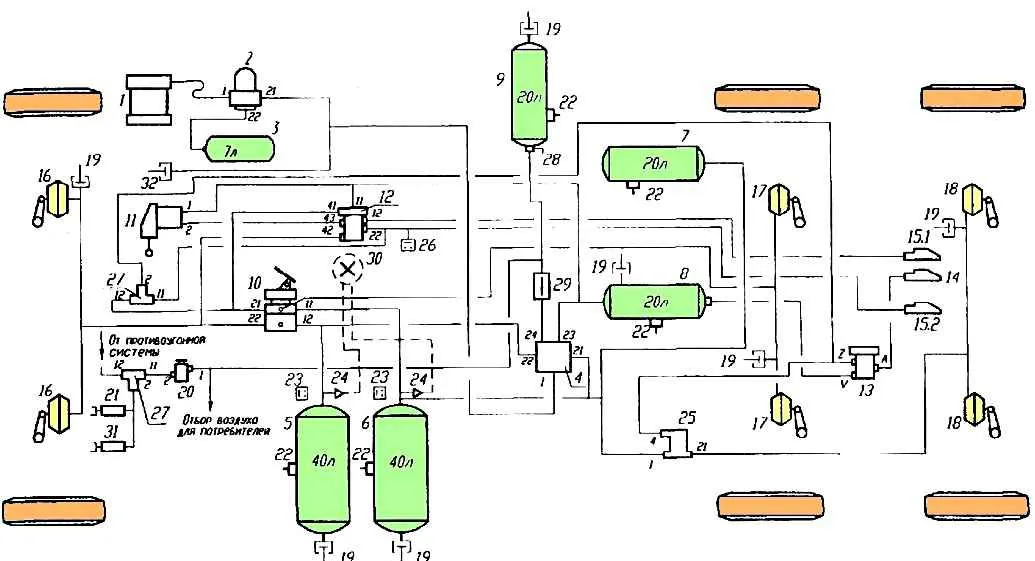
Principal diagram of the pneumatic drive of the brakes: 1 - compressor; 2 - pressure regulator with adsorber (compressed air dryer); 3 - regeneration receiver; 4 - four-circuit protective valve; 5 - front operating circuit receiver; 6 - receiver of the rear working circuit; 7 - receiver of the rear working circuit; 8 - receiver for pneumatic parking brake and trailer power supply; 9 - receiver of the consumer circuit; 10 valve of the service brake system; 11 - pneumatic parking brake valve; 12 - valve for controlling trailer brakes via a two-wire drive; 13 - valve for controlling trailer brakes via a single-wire drive; 14 - automatic connecting head for single-wire trailer drive; 15 - automatic connecting head for two-wire connection trailer ode; 15.1 - head of the supply line (red cover); 15.2 - control line head (yellow cover); 16 - brake chamber of the front axle; 17 - brake chamber of the middle axle; 18 - rear axle brake chamber; 19 - control valve; 20 - auxiliary brake system valve; 21 - engine brake flap cylinder; 22 - condensate drain valve; 23 - emergency pressure sensor; 24 - pressure sensor; 25 - brake light sensor, 26 - accelerator valve; 27 - double-line valve; 28 - tire crane; 29 - check valve; 30 - pressure gauges in the driver’s cabin; 31 - engine stop cylinder (on the injection pump); 32 - towing valve (under the front cross member)
Diagram of pneumatic brake drive for MAZ-631705, 631708, 642505, 642508
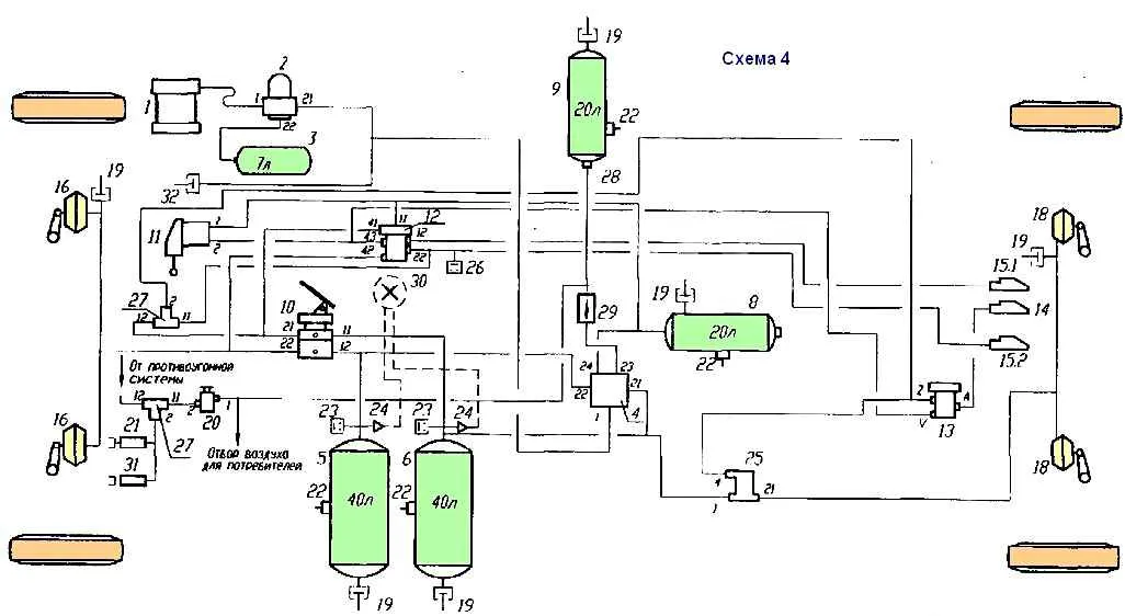
Principal diagram of the pneumatic drive of the brakes: 1 - compressor; 2 - pressure regulator with adsorber (compressed air dryer); 3 - regeneration receiver; 4 - four-circuit protective valve; 5 - front operating circuit receiver; 6 - receiver of the rear working circuit; 7 - receiver of the rear working circuit; 8 - receiver for pneumatic parking brake and trailer power supply; 9 - receiver of the consumer circuit; 10 valve of the service brake system; 11 - pneumatic parking brake valve; 12 - valve for controlling trailer brakes via a two-wire drive; 13 - valve for controlling trailer brakes via a single-wire drive; 14 - automatic connecting head for single-wire trailer drive; 15 - automatic connecting head for two-wire trailer drive; 15.1 supply line head (red cover); 15.2 - control line head (yellow cover); 16 - front axle brake chamber; 17 - brake chamber of the middle axle; 18 - rear axle brake chamber; 19 - control valve; 20 - auxiliary brake system valve; 21 - engine brake flap cylinder; 22 - condensate drain valve; 23 - emergency pressure sensor; 24 - pressure sensor; 25 - brake light sensor, 26 - accelerator valve; 27 - two-line valve; 28 - tire crane; 29 - check valve; 30 - pressure gauges in the driver’s cabin; 31 - engine stop cylinder (on the injection pump); 32 - towing valve (under the front cross member)
Diagram of a MAZ-53 1605 car with a transmission parking brake
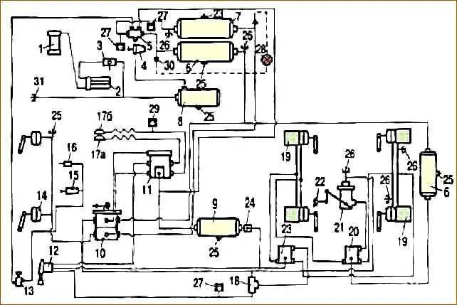
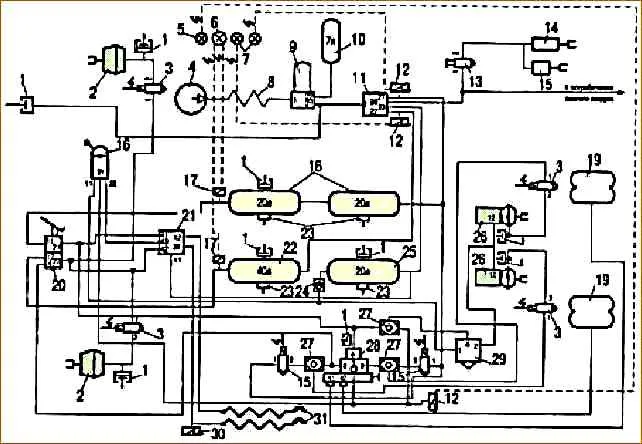
Fig. 5. Schematic diagram of the pneumatic brake drive of three-axle MAZ vehicles without ABS: 1 – compressor; 2 – moisture separator; 3 – pressure regulator; 4 – antifreeze; 5 – four-circuit safety valve; 6 – air cylinder of the rear circuit; 7 – front air cylinder; 8 – common air cylinder (wet); 9 – air cylinder of the parking system and semi-trailer; 10 – brake valve; 11 – semi-trailer brake control valve; 12 – emergency brake control valve; 13 – auxiliary brake control valve; 14 – front brake chamber; 15 – damper pneumatic cylinder; 16 – pneumatic cylinder of the injection pump bracket; 17 – connecting heads; 18 – two-line valve; 19 – brake chamber with spring energy accumulator; 20 – accelerator valve of the working system; 21 – brake force regulator; 22 – elastic element of the brake force regulator (RTS); 23 – accelerator valve of the emergency system; 24 – check valve; 25 – condensate drain valve; 26 – control valve; 27, 29, 30 – sensors; 28 – pressure gauge; 31 – towing valve
Schematic diagram of the pneumatic brake drive of three-axle MAZ vehicles without ABS
Schematic diagram of the pneumatic brake drive of two-axle MAZ vehicles without ABS
Schematic diagram of the pneumatic brake drive of two-axle MAZ vehicles with ABS
Schematic diagram of the pneumatic brake drive of two-axle MAZ 5440 vehicles with ABS
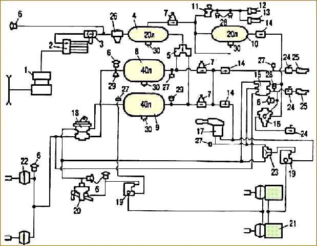
Diagram of a pneumatic brake drive for two-axle vehicles with a double safety valve