Turbocharger - uses the energy of exhaust gases for operation, consists of a single-stage centrifugal compressor and a radial centripetal turbine
The main units of the turbocharger are:
bearing housing, rotor, compressor housing and turbine housing.
The turbine and compressor wheels are located at opposite ends of the rotor shaft, cantilevered relative to the bearings.
The impeller 16 of the centrifugal compressor is of a semi-open type, with radial blades, cast from an aluminum alloy. It is pressed onto the shaft and secured with a nut.
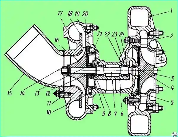
Fig. 1. Turbocharger: 1 - turbine housing; 2 - nozzle ring; 3 - turbine wheel; 4 - turbine sealing ring; 5 - turbine housing spacer; 6 - bearing housing; 7 - rotor shaft; 8 - thrust sleeve; 9 - thrust flange; 10 - bearing housing cover; 11 - branch pipe gasket; 12 - oil deflector; 13 - rotor sealing ring; 14 - compressor wheel nut; 15 - inlet pipe; 16 - compressor wheel; 17 - compressor housing; 18 - diffuser; 19 - compressor housing cover; 20, 21 - sealing rings; 22 - thrust ring; 23 - bushing; 24 - washer
The compressor has a vaneless diffuser mounted on the compressor housing 17, which is made of aluminum alloy in the form of two semi-snail air collectors.
The outlet pipes of the compressor housing are adapted for connection to the engine suction manifold with durite hoses with clamps.
The inlet pipe 15 with a protective mesh is attached to the end of the compressor housing.
The turbine impeller 3, made of heat-resistant alloy, is connected to the shaft by friction welding.
Maintenance of the turbocharger
During operation, the turbocharger does not require any adjustments. However, during operation, its operation should be systematically monitored:
- - monitor the pressure gauge for oil circulation through the turbocharger and the oil pressure in the turbocharger lubrication system;
- - periodically monitor the turbocharger operation by ear immediately after stopping the engine;
- - regularly check the ease of rotation of the turbocharger rotor, for which first unscrew the three nuts, remove the inlet pipe and gasket.
If the rotating parts touch fixed parts, remove the turbocharger from the engine, disassemble, clean from carbon deposits and wash.
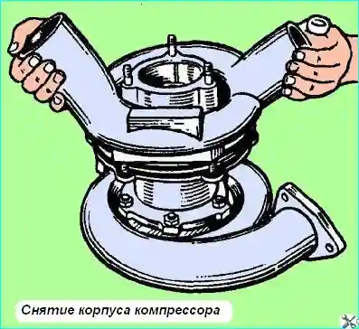
Figure 2. Removing the compressor housing
To detect deviations from normal operation or for post-repair inspection, you can check the turbocharger on the engine by boost pressure. To do this, unscrew the plug on the left intake manifold and attach a pressure gauge to the hole.
To obtain stable readings, a nozzle with a hole with a diameter of 0.5 mm must be installed at the input to the pressure gauge.
When operating under full load at a crankshaft speed of 2100 min-1, the excess boost pressure should be 0.6-0.8 kgf/cm².
When the load is reduced or the speed decreases, the boost pressure should decrease smoothly.
Disassembly and assembly of the turbocharger is carried out in a specially adapted room that provides conditions that exclude contamination of its parts, especially the ingress of sand and dust on the rubbing surfaces.
Disassembly should be performed in the following sequence:
- disconnect the gas, air and oil lines from the turbocharger.
After disconnecting the exhaust line, secure the nozzle ring 2 (see Fig. 1) from falling out with two diametrically located nuts;
- - unscrew the four bolts securing the bracket to the flywheel housing and remove the turbocharger from the engine together with the bracket;
- - unscrew the four nuts securing the bracket, remove the bracket and its gasket;
- - unscrew the three nuts securing the inlet pipe, remove the pipe and gasket;
- - unscrew the six nuts securing the compressor housing 17, remove the housing assembled with the diffuser;
- - rotate the rotor 7 by hand, check the ease of its rotation (do not touch rotating parts for stationary parts).
This - check should be done several times in the extreme positions of the rotor, selecting its axial and radial clearances successively in one direction and the other.
If as a result of this check and inspection of the compressor parts it is revealed that the cause of the contact were the compressor parts, disassemble and clean only the compressor, clean, wash and assemble the compressor parts.
Before assembly, inspect and, if necessary, replace the rubber sealing ring of the compressor housing;
- - if the rotor interference is not eliminated with the compressor parts removed, it is necessary to remove the turbine parts, for which unscrew the six nuts securing its housing 1 and disconnect the turbine housing assembled with the nozzle ring 2;
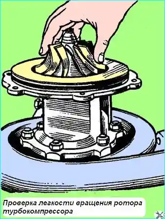
Fig. 3. Checking the ease of rotation of the turbocharger
- - check the ease of rotation of the rotor in the bearings with the turbine housing removed. If the interference is now eliminated, clean and rinse the turbine housing, then assemble the turbocharger;
- - if the interference is not eliminated after removing the turbine and compressor housings, remove and clean the rotor in the following order:
- - unscrew nut 14 of the compressor wheel;
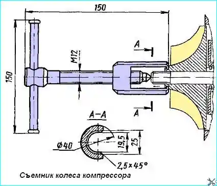
Fig. 4. Compressor wheel puller
- - remove the compressor wheel with a special puller (Fig. 4). The location of the nut relative to the wheel and the wheel relative to the shaft is indicated by marks.
If the marks are not preserved, they should be placed before disassembling in such a way that the location of these parts relative to each other does not change during subsequent assembly;
- - unscrew the two bolts securing the cover 10 of the bearing housing, remove the cover with the sealing ring 21, screwing the bolts into the threaded holes of the cover;
- - remove the oil deflector;
- - unscrew the three screws securing the thrust flange 9, remove the thrust flange and thrust sleeve from the shaft;
- - remove the turbocharger rotor towards the turbine;
- - remove the bearing retaining ring, remove the washer and sleeve 8 of the bearing first from one side and then from the other side of the bearing housing;
- - remove the spacer turbines;
- - remove carbon deposits from parts with a wooden scraper, after placing them in a bath with kerosene for 3-4 hours.
- - clean the flow parts with a hair brush, wash all parts with gasoline.
Carefully inspect the turbine and compressor wheels; if there are cracks on the blades or disks, replace the rotor assembly;
- - if necessary, unscrew the two nuts securing the nozzle ring 2, remove it, inspect it and the turbine housing; if there are cracks, replace the parts.
After cleaning or repairing, assemble the turbocharger in the reverse order.
Before assembly, wash all turbocharger parts with kerosene and blow each part with compressed air, lubricate the bearing bushings and rotor shaft with engine oil.
When assembling the rotor, align the marks on the oil deflector and thrust sleeve with the line on the shaft.
Heat the compressor wheel to 80-100˚C before pressing it onto the shaft.
Tighten the compressor wheel nut until the marks on it and on the compressor wheel align.
Tighten all fasteners and secure them securely. The thrust flange screws are secured by punching.
After assembling the turbocharger, make sure that the rotor does not touch any stationary parts during rotation.
When installing the turbocharger on the engine, connect all lines (gas, air, oil), after making sure that they are clean and free of foreign objects.
Turbocharger Maintenance
Carry out turbocharger maintenance every 3000 hours of engine operation.
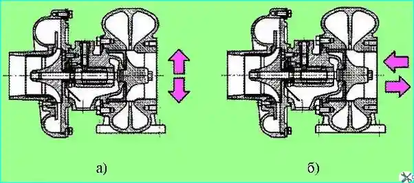
Fig. 5. Checking rotor play: (a) - radial; (b) - axial
During maintenance, check the axial and radial play of the rotor using an indicator.
Play is defined as the difference in indicator readings when the shaft is deflected in two mutually opposite directions (Fig. 5).
Permissible maximum values of play are axial - 0.20 mm, radial - 0.80 mm. If the clearances are greater than the maximum values, the turbocharger must be replaced.
Once a year, remove deposits from the compressor turbine housing and from the impellers.
Clean compressor parts with gasoline, turbine parts - with a decarbonizer.
When installing a turbocharger on an engine, carefully monitor the cleanliness of the pipelines connected to the turbocharger and the absence of objects and debris in them.
After installing the turbocharger, fill the bearing housing with clean oil through the oil supply hole.
Carefully monitor the absence of suction and leaks in the air, gas, oil pipelines and their connections.
It should be borne in mind that the optimal operating mode of the turbocharger is carried out in the range of a higher engine crankshaft speed.


