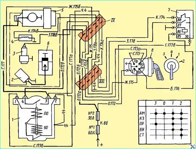
The electrical circuit of the starting heater is shown in Fig. 1
When the handle of the switch 8 is turned to position 1, the electric motor 5 of the pumping unit and the fuel solenoid valve 3 are switched on
The boiler is purged and the fuel is heated, i.e. the boiler is prepared for operation.

Heater connection diagram: 1 - contactor; 2 - transistor switch; 3 - fuel solenoid valve; 4 - thermoelectric heater; 5 - pumping unit electric motor; 6 - spark plug; 7 - heater on relay P9; 8 - heater switch; IV, XVI - plug connectors
This switch position is fixed, then the switch handle is moved to position 2, in which the transistor switch 2 is additionally switched on.
The fuel ignites through the spark plug 6 and the heater starts working.
Position 2 of the switch handle 8 is not fixed.
After removing the hand from the handle, the latter returns to position 1, which is the working position and is on during the entire operation of the heater.
After the engine warms up, the switch handle is moved to position 3, in which the electric motor and the thermoelectric heater operate, and the boiler is purged.
Position 0 - everything is off.
The operation of the heating system products can be easily traced using the specified diagram.
Maintenance of the starting heater
In During operation, the spark plug, the thermoelectric heater and the fuel solenoid valve may fail. These products are non-separable and are replaced when they fail.
The transistor switch is made of electronic elements, is hermetically sealed, does not require maintenance and is also not repaired.
The electric motor of the pump unit is not serviced during operation.
Since the electric motor does not operate for a long time, it ensures normal operation of the heater during vehicle runs during several major repairs.


