The steering includes a steering mechanism 10 (Fig. 1) with a built-in distributor, a column 2, a steering wheel 1, a power cylinder 9, a pump 3, an oil tank 4, and hoses.
To diagnose the operation of the hydraulic steering system, you need to remember the following:
- - when the spool passes the neutral position (turn the steering wheel left - right from the middle position) and the temperature of the working fluid (50 ± 5) ° C, the pressure in the pressure line should not exceed 0.3 MPa (3 kgf/cm 2);
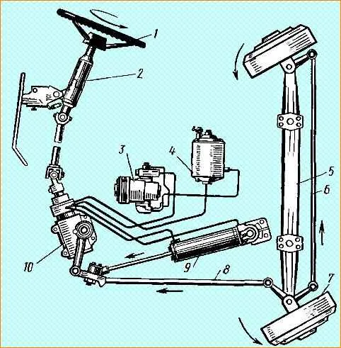
Steering layout diagram: 1 - steering wheel; 2 - steering column; 3 - pump; 4 oil tank; 5 - front axle beam; 6 - transverse steering rod; 7 brake drum; 8 - longitudinal steering rod; 9 - power cylinder of the hydraulic booster; 10 - steering mechanism
- - at a crankshaft rotation speed of 1500 min -1 and the extreme (left or right) position of the steered wheels, the maximum pressure in the pressure line should not exceed 11 MPa (110 kgf/cm 2< /sup>).
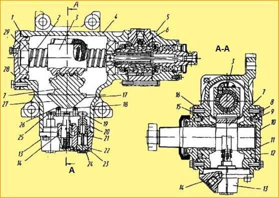
The axis of the outer surface of the liners 12 is shifted relative to the axis of the hole of the bearings 13 by the amount of eccentricity “h”, which makes it possible to adjust the gearing by rotating the liners 12.
The tension of bearings 1 is adjusted using spacers 9.
Steering mechanism: 1 - bearings; 2 - screw; 3 - body; 4 - nut-rack; 5 - balls; 6 - seal; 7 - torsion bar: 8 - gear sector; 9 - adjusting shims; 10 - cover; 11 - holes; 12 - eccentric bearings, 13 - plain bearing; 14 - pin; 15 - pressure limiting valve cover); 16 – plug; 17 - clamp; 18 - thrust ring; 19 - cover; 20 - cuff 21 - nut
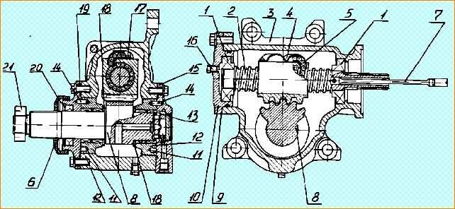
The steering mechanism with a built-in distributor and a valve for limiting the pressure of the working fluid is shown in Fig. 2.
Steering mechanism: 1 - shims; 2 - screw; 3 - nut-rack; 4 - body; 5 - distributor; 6 - channel; 7 - sector; 8.15 - eccentric liners; 9 - pin; 10,16, 28 - cover; 11, 29 - bearings; 12 - hole; 13 - pressure limitation valve; 14 - ring boring; 17, 27 - side face; 18, 26 - roller: 19, 25 - lever; 20 - rod; 21- nut; 22 - plug; 23 - body; 24 - lock nut
On cars it is possible to install a steering mechanism (Fig. 3).
The power steering distributor is of the spool type, built into the steering mechanism.
In housing 6 (Fig. 4) of the spool there are three annular bores C, E, D.
The middle annular bore E is connected to channel “B” for supplying working fluid from the pump, and the extreme ones C and D are connected to channel A for draining fluid to the drain.
In three reaction chambers of the spool body b, plungers 25 are placed freely, with the possibility of axial movement.
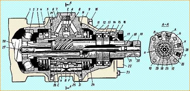
Power steering distributor: 1 - steering gear housing; 2,4,11,13 - bearings; 3 - nut; 5- O-ring; b- distributor housing; 7 - check valve; 8 - ball; 9 - distributor cap; 10.23 - bolts; 12 - bushing; 14 - adjusting gaskets; 15 - cuff; 16 - retaining ring; 17 - ring; 18 - input shaft; 19 - pin; 20 - torsion bar; 21 - sealing ring; 22 - oil seal cover; 24 - adjusting gasket; 25 - plunger; 26 - spool; 27 - pin; 28 - screw; A - channel for draining working fluid to drain; 11 - channel for supplying working fluid from the pump; K, F - channels for supply (discharge) of working fluid to the cavities of the power cylinder; C, J, D - annular borings; M, N - drillings for connecting the cavities of thrust bearings with a drain; n - gap
In the central hole of the housing there is a spool 26, secured by thrust bearings 4 and 11 on a sleeve 12, which is connected by splines without lateral clearance to the steering gear screw 28 with the possibility of axial movement, and by a screw connection to the input shaft 18.
The spline connection of the input shaft 18 and screw 28 is made with a gap of n.
The gap is selected from the condition of ensuring full spool travel.
In addition, the input shaft 18 is connected by a torsion bar 20 to a screw 28 steering mechanism.
Check valve 7 is screwed into the channel of the middle annular bore E.
Power steering works as follows.
When the car moves in a straight line, spool 5 (Fig. 5) occupies a neutral position and the working fluid from pump 18 flows to the middle annular bore E (see Fig. 4) of the spool body through oil line 11 (see Fig. 5) and through extreme bores C and D (see Fig. 4) - to drain through oil line 13 (see Fig. 5), while filling the reaction chambers between the plungers 6 and through channels K and G (see Fig. 4) in the housing along oil lines 8 (see Fig. 5) and 12 - cavities of power cylinder 17.
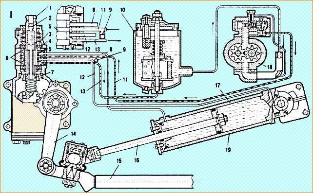
Diagram of operation of the power steering during straight-line motion: 1 - input shaft; 2 - torsion bar; 3 - bushing; 4 - bearing; 5 - spool; 6 - plungers; 7 - shaft; 8,11,12,13 - oil lines; 9 - check valve; 10 - tank; 14 - steering bipod; 15 - steering longitudinal rod; 16 - rod; 17 power cylinder; 19 - pump; 19 - piston; p - gap in the spline connection of shaft 7 with the input shaft
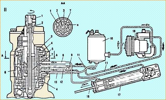
Diagram of operation of the power steering when turning left: 1 - input shaft; 2 - torsion bar; 3 - bushing; 4 - bearing; 5 - spool; 6 - plungers; 7 - shaft; 8,11,12,13 - oil lines; 9 - check valve; 10 - tank; 14 - steering bipod; 15 - steering longitudinal rod; 16 - rod; 17 power cylinder; 19 - pump; 19 - piston; p - gap in the spline connection of shaft 7 with the input shaft
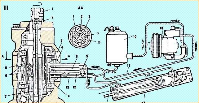
Diagram of operation of the power steering when turning to the right: 1 - input shaft; 2 - torsion bar; 3 - bushing; 4 - bearing; 5 - spool; 6 - plungers; 7 - shaft; 8,11,12,13 - oil lines; 9 - check valve; 10 - tank; 14 - steering bipod; 15 - steering longitudinal rod; 16 - rod; 17 power cylinder; 19 - pump; 19 - piston; p - gap in the spline connection of shaft 7 with the input shaft
When the steering wheel is turned counterclockwise and, therefore, the input shaft 1, thanks to the screw connection, the sleeve 3 with the spool 5 attached to it moves along the splines of the shaft 7 in the axial direction upward.
At the initial moment of displacement, when the pressure in the system is insignificant, the force on the steering wheel is mainly created by torsion bar 2, which directly acts on input shaft 1.
The screw connection moves the spool and is practically not loaded.
When the spool is displaced, the value of which is limited by the gap n in the spline connection, the access of the working fluid to the annular bore C stops (see Fig. 4).
The working fluid from the pump is supplied to the middle bore E, and then through channel K in the housing and the oil pipe 12 (see Fig. 5) enters the sub-piston cavity of the power cylinder 17, as a result of which the piston 19 with the rod 16 moves, turning along clockwise, the sector shaft with the steering bipod 14, and through the steering longitudinal rod 15 turns the steered wheels to the left.
From the rod cavity of the power cylinder, the working fluid through oil line 8 and channel E (see Fig. 4) in the housing enters the annular bore D and then through oil line 13 (see Fig. 5) into the oil tank 10.
When the steering wheel is turned clockwise, bushing 3 with spool 5 moves down.
The supply of working fluid to the annular bore D (see Fig. 4) is stopped.
The working fluid from the pump enters the middle bore E and then through channel F and oil line 8 (see Fig. 5) into the rod cavity of the cylinder.
The piston and rod move, turning the steering arm 14 counterclockwise, and through the longitudinal rod turns the steered wheels to the right.
From the sub-piston cavity of the cylinder, the working fluid flows through oil line 12 and channel K (see Fig. 4) in the housing into the annular bore C and then through oil line 13 (see Fig. 5) into the oil tank.
As the moment of resistance to turning of the steered wheels increases, the pressure of the working fluid in the system and, consequently, in the reaction chambers increases, which causes a proportional increase in the force on the steering wheel.
This way, the driver gets a “feeling of the road.”
When the force is removed from the steering wheel, torsion bar 2 and plungers 6 return the spool to the neutral position.
When the pump is not working or the power steering is insufficiently effective, a gap (n) is selected in the splined connection of input shaft 1 with shaft 7 and the force from the steering wheel is transmitted as in steering without power assistance.
In this case, check valve 9 bypasses the working fluid from one cavity of the power cylinder to another.
Possible steering malfunctions and methods for eliminating them
Malfunction Methods of elimination
Increased force on the steering wheel when turning right and left:
- Reduced oil level in the tank - Open the tank and, with the engine running, fill it with oil at least to the upper mark on the dipstick. Check the system for leaks and, if necessary, repair damage
- There is air in the hydraulic system - Check the suction pipe and the pump shaft seal for leaks. Bleed the hydraulic steering system and add oil
- The power cylinder piston seal is damaged - Replace the power cylinder piston seal and, if necessary, tighten the nut securing the piston to the rod
- The operation of the flow and pressure valve of the pump is impaired (foreign particles have entered under the ball or between the plunger and the body of the flow and pressure valve) - Remove the spring-loaded plunger from the pump, disassemble, wash and check. Wedging of the plunger in the pump body is not allowed
- The pressure limiting valve plunger does not return after turning the steering wheels to the extreme left or right position - Remove the pressure limiting valve, rinse, clean, remove jammed plungers
Poor vehicle control when driving straight:
- Reduced oil level in the tank - Fill the tank with oil to the upper mark, with the engine running
- If the oil level is normal, air enters the system - Eliminate air leaks and bleed the hydraulic system
- The steering mechanism itself is loose or the spring ladders are loose - Check and fix the problem
- Wheel toe is out of alignment - Adjust toe
- Increased play of the steering shaft - Adjust the tension of the screw bearings and the engagement gap
- Radial play in the steering column driveshaft - Replace the driveshaft
High force on the steering wheel at high rotation speeds:
- The operation of the flow and pressure valve is impaired - Remove the plunger from the pump, disassemble, wash and check
- The pump does not provide sufficient oil supply due to worn parts - Replace the pump
Vibration on the steering wheel while driving:
- Unbalance of the steering wheels or brake drums - Balance or replace the steering wheels and brake drums
Spontaneous rotation of the steering wheels to the extreme position:
- Input shaft and spool drive bushing are not connected correctly - Remove the distributor and correctly connect the input shaft to the spool drive bushing
Increased noise during pump operation:
- Low oil level in the tank
- Air in oil - Fill the reservoir with oil
- Check the suction pipe and the pump shaft seal for leaks.
- Bleed air from the steering hydraulic system and add oil
")

")
")
")
")
")
")
")